AUTOMATIC TRANSMISSION ASSEMBLY INSTALLATION
PROCEDURE
-
INSPECT TORQUE CONVERTER ASSEMBLY
-
INSTALL TORQUE CONVERTER ASSEMBLY
-
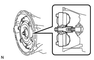
Engage the splines of the input shaft and turbine runner.
-
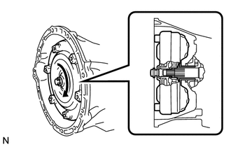
Engage the splines of the stator shaft and stator while turning the torque converter assembly.
Tech Tips
If the stator shaft splines are difficult to engage with the stator splines, move the torque converter back approximately 10 mm (0.394 in.) and engage the splines while rotating the torque converter assembly.
-
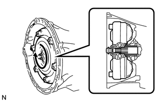
Turn the torque converter assembly to engage the key of the oil pump drive gear into the slot on the torque converter assembly.
-
Clean the drive plate and torque converter setting bolt holes.
-
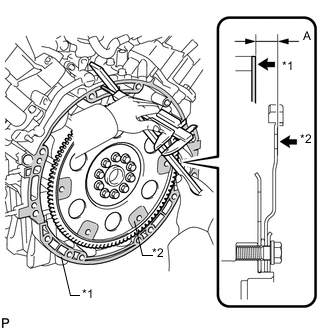
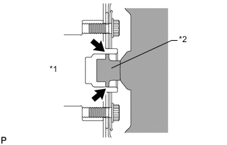
Text in Illustration *1 Engine Surface *2 Drive Plate Surface Using a vernier caliper and straightedge, measure dimension A between the transmission contact surface of the engine and the torque converter contact surface of the drive plate.
-
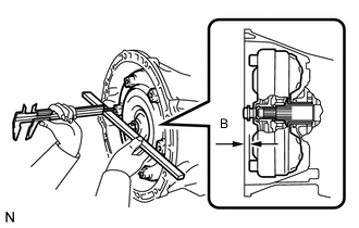
Using a vernier caliper and straightedge, measure dimension B shown in the illustration and check that dimension B is more than dimension A, which was measured in the previous step.
Standard A + 1 mm (0.0394 in.) or more Note
-
Make sure to deduct the thickness of the straightedge.
-
If the transaxle is installed to the engine with the torque converter not sufficiently inserted, the torque converter may be damaged.
-
-
-
INSTALL ENGINE REAR MOUNTING INSULATOR
-
Install the engine rear mounting insulator with the 4 bolts.
- Torque:
- 40 N*m { 408 kgf*cm, 30 ft.*lbf }
-
-
INSTALL AUTOMATIC TRANSMISSION ASSEMBLY
-
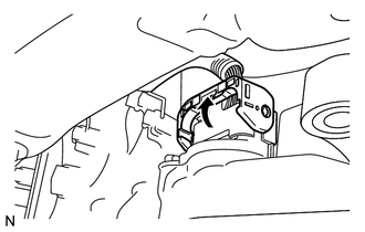
Text in Illustration *1 Crankshaft *2 Torque Converter Centerpiece Apply clutch spline grease to the circumference of the crankshaft contact surface with the torque converter centerpiece.
Clutch spline grease Toyota Genuine Clutch Spline Grease or equivalent Maximum spread About 1 g (0.0353 oz.) -
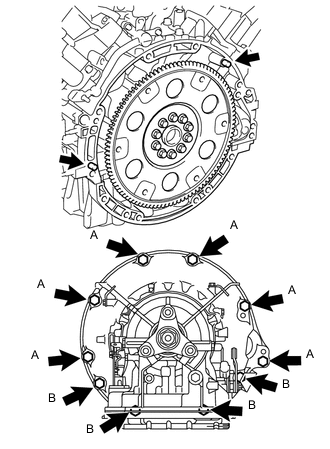
Confirm that 2 knock pins are on the transmission contact surface of the engine block before transmission installation.
- Torque:
- for Bolt A (17 mm head bolt)
- 71 N*m { 724 kgf*cm, 52 ft.*lbf }
- for Bolt B (14 mm head bolt)
- 37 N*m { 377 kgf*cm, 27 ft.*lbf }
Note
-
Make sure that the mark is positioned as shown in the illustration.
-
Do not use excess force to pry on the automatic transmission assembly.
-
-
INSTALL DRIVE PLATE AND TORQUE CONVERTER SETTING BOLT
-
Turn the crankshaft to gain access to the installation locations of the 6 torque converter setting bolts and install each bolt while holding the crankshaft pulley bolt with a wrench.
- Torque:
- 48 N*m { 489 kgf*cm, 35 ft.*lbf }
Note
First install the black colored bolt, and then the remaining 5 silver colored bolts.
-
-
CONNECT WIRE HARNESS AND CONNECTOR
-
Tilt down the automatic transmission assembly.
-
Connect the park/neutral position switch connector.
-
Connect the transmission wire connector.
Tech Tips
Push up the lever until the claw of the transmission wire connector makes a connection sound.
-
Attach the 5 harness clamps to the automatic transmission assembly.
-
Tilt up the automatic transmission assembly.
-
Install the bolt and ground wire to the automatic transmission assembly.
- Torque:
- 5.4 N*m { 55 kgf*cm, 48 in.*lbf }
-
-
INSTALL ENGINE REAR MOUNTING MEMBER
-
Install the engine rear mounting member to the body with the 6 bolts.
- Torque:
- 35 N*m { 354 kgf*cm, 26 ft.*lbf }
-
Install the engine rear mounting member to the automatic transmission assembly with the 4 nuts.
- Torque:
- 14 N*m { 138 kgf*cm, 10 ft.*lbf }
-
-
CONNECT OIL COOLER TUBE INLET AND OUTLET
-
Temporarily install the oil cooler tube inlet and oil cooler tube outlet.
-
Install the 2 clamps with the 2 bolts.
- Torque:
- 5.5 N*m { 56 kgf*cm, 49 in.*lbf }
-
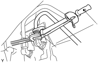
Using a union nut wrench, tighten the union nuts of the oil cooler tube inlet and oil cooler tube outlet.
- Torque:
- 44 N*m { 450 kgf*cm, 33 ft.*lbf }
Note
Use the formula to calculate special torque values for situations where a union nut wrench is combined with a torque wrench Click here.
-
-
INSTALL TRANSMISSION CONTROL SHAFT LEVER RH
-
Install the transmission control shaft lever RH together with the floor shift gear shifting rod subassembly with the nut.
- Torque:
- 16 N*m { 160 kgf*cm, 12 ft.*lbf }
-
-
CONNECT FLOOR SHIFT GEAR SHIFTING ROD SUB-ASSEMBLY
-
Temporarily connect the floor shift gear sifting rod sub-assembly to the connecting rod swivel with the nut.
Tech Tips
The nut will be tightened to a torque specification during the shift lever position adjustment procedure.
-
-
INSTALL STARTER ASSEMBLY
-
INSTALL EXHAUST MANIFOLD
-
for 1UR-FSE:
-
for 1UR-FE:
-
-
CONNECT CABLE TO NEGATIVE BATTERY TERMINAL
Note
When disconnecting the cable, some systems need to be initialized after the cable is reconnected Click here.
-
INSTALL COWL TOP VENTILATOR LOUVER
-
ADD AUTOMATIC TRANSMISSION FLUID
-
ADJUST SHIFT LEVER POSITION
-
INSPECT SHIFT LEVER POSITION
-
CHECK RESET MEMORY