IGNITION COIL AND SPARK PLUG INSTALLATION
PROCEDURE
-
INSTALL SPARK PLUG
-
Using a 16 mm plug wrench, install the 8 spark plugs.
- Torque:
- 21 N*m { 214 kgf*cm, 15 ft.*lbf }
-
-
INSTALL IGNITION COIL ASSEMBLY
-
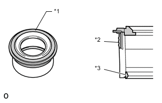
*1 Upper Surface *2 Outer Lip *3 Inner Lip Perform a visual inspection on the spark plug tube gasket.
Standard Inspection Area Inspection Result Upper surface No scratches or deformation Outer lip No scratches or deformation Inner lip No scratches -
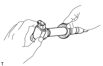
Set each spark plug tube gasket on each ignition coil assembly.
-
After installing each spark plug tube gasket, securely insert each ignition coil assembly.
-
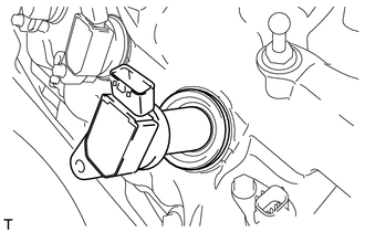
Install the 8 bolts.
- Torque:
- 10 N*m { 102 kgf*cm, 7 ft.*lbf }
-
Connect the 8 ignition coil ignition coil assembly connectors.
-
-
INSTALL AIR CLEANER ASSEMBLY RH
-
INSTALL AIR CLEANER ASSEMBLY LH
-
INSTALL SKID CONTROL ECU BRACKET
-
INSTALL BATTERY TRAY
-
Install the battery tray with the 3 bolts.
- Torque:
- 5.4 N*m { 55 kgf*cm, 47 in.*lbf }
-
-
INSTALL BATTERY
-
Install the battery.
-
Install the battery insulator.
-
Install the No. 2 battery clamp bolt and battery clamp with the nut.
- Torque:
- 2.9 N*m { 30 kgf*cm, 26 in.*lbf }
-
Connect the battery cable clamp.
-
Connect the positive (+) battery cable to the battery terminal.
- Torque:
- 5.6 N*m { 57 kgf*cm, 50 in.*lbf }
-
-
INSTALL INTAKE AIR CONNECTOR PIPE
-
Align the protrusion of the intake air resonator with the cutout of the bracket and insert the protrusion.
-
Install the intake air connector pipe with the 3 hose clamps.
- Torque:
- for intake air connector pipe and throttle body
- 4.8 N*m { 49 kgf*cm, 42 in.*lbf }
- for intake air connector pipe and air cleaner cap
- 3.8 N*m { 39 kgf*cm, 34 in.*lbf }
Tech Tips
-
Insert the protrusion of the intake air connector pipe into the hole of the hose clamp.
-
The intake air connector pipe and throttle body clamp can be tightened within the range of 4.0 N*m (41 kgf*cm, 35 in.*lbf) to 5.5 N*m (56 kgf*cm, 49 in.*lbf), and the intake air connector pipe and air cleaner cap clamp can be tightened within the range of 2.0 N*m (20 kgf*cm, 18 in.*lbf) to 5.5 N*m (56 kgf*cm, 49 in.*lbf).
-
Attach the 2 wire harness clamps.
-
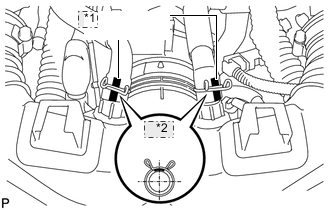
*1 White Paint *2 Upper Connect the No. 1 and No. 2 ventilation hoses to the intake air connector pipe.
Tech Tips
-
Position the claws of the clamps as shown in the illustration.
-
Install the clamps so that they are within the hose's paint marks.
-
-
-
INSTALL NO. 1 AIR CLEANER INLET
-
INSTALL ENGINE ROOM SIDE COVER RH
-
Install the engine room side cover RH with the 5 clips.
-
-
INSTALL ENGINE ROOM SIDE COVER LH
-
Install the engine room side cover LH with the 5 clips.
-
-
INSTALL AIR CLEANER INLET COVER SUB-ASSEMBLY
-
INSTALL V-BANK COVER SUB-ASSEMBLY
-
CONNECT CABLE TO NEGATIVE BATTERY TERMINAL
Note
When disconnecting the cable, some systems need to be initialized after the cable is reconnected Click here.
-
INSTALL COWL TOP VENTILATOR LOUVER RH