EXHAUST MANIFOLD(for 2WD) REMOVAL
PROCEDURE
-
REMOVE COWL TOP VENTILATOR LOUVER
-
PRECAUTION
Note
After turning the engine switch off, waiting time may be required before disconnecting the cable from the battery terminal. Therefore, make sure to read the disconnecting the cable from the battery terminal notice before proceeding with work Click here.
-
DISCONNECT CABLE FROM NEGATIVE BATTERY TERMINAL
Note
When disconnecting the cable, some systems need to be initialized after the cable is reconnected Click here.
-
REMOVE FRONT EXHAUST PIPE ASSEMBLY
-
REMOVE FRONT SUSPENSION MEMBER REINFORCEMENT LH
-
REMOVE FRONT SUSPENSION MEMBER REINFORCEMENT RH
Tech Tips
Use the same procedure described for the LH side.
-
REMOVE V-BANK COVER SUB-ASSEMBLY
-
REMOVE AIR CLEANER INLET COVER SUB-ASSEMBLY
-
REMOVE NO. 1 AIR CLEANER INLET
-
REMOVE INTAKE AIR CONNECTOR PIPE
-
REMOVE V-RIBBED BELT
-
REMOVE ENGINE ROOM SIDE COVER RH
-
REMOVE ENGINE ROOM SIDE COVER LH
-
REMOVE NO. 1 ENGINE UNDER COVER
-
REMOVE FRONT SUSPENSION MEMBER PROTECTOR LOWER
-
REMOVE NO. 1 EXHAUST PIPE SUPPORT BRACKET SUB-ASSEMBLY
-
REMOVE GENERATOR ASSEMBLY
-
REMOVE STEERING SLIDING YOKE WITH SHAFT SUB-ASSEMBLY (w/ VGRS)
-
REMOVE STEERING SLIDING YOKE WITH SHAFT SUB-ASSEMBLY (w/o VGRS)
-
REMOVE STEERING INTERMEDIATE SHAFT (w/o VGRS)
-
REMOVE NO. 2 STEERING INTERMEDIATE SHAFT ASSEMBLY (w/ VGRS)
-
REMOVE NO. 2 STEERING INTERMEDIATE SHAFT ASSEMBLY (w/o VGRS)
-
REMOVE ENGINE OIL LEVEL DIPSTICK GUIDE
-
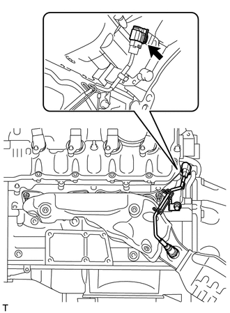
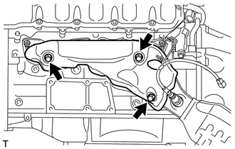
REMOVE NO. 1 EXHAUST MANIFOLD HEAT INSULATOR
-
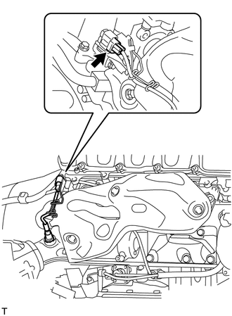
Disconnect the air fuel ratio sensor connector.
-
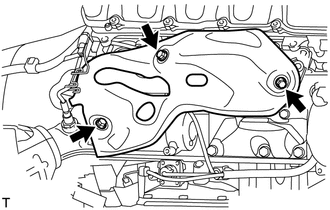
Remove the 3 bolts and No. 1 exhaust manifold heat insulator.
-
-
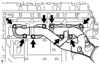
REMOVE EXHAUST MANIFOLD SUB-ASSEMBLY RH
-
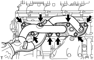
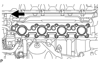
Remove the 8 nuts and exhaust manifold RH.
-
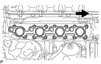
Remove the gasket.
Text in Illustration 
Front
-
-
REMOVE NO. 2 EXHAUST MANIFOLD HEAT INSULATOR
-
Disconnect the air fuel ratio sensor connector.
-
Remove the 3 bolts and No. 2 exhaust manifold heat insulator.
-
-
REMOVE EXHAUST MANIFOLD SUB-ASSEMBLY LH
-
Remove the 8 nuts and exhaust manifold LH.
-
Remove the gasket.
Text in Illustration Front
-
-
REMOVE AIR FUEL RATIO SENSOR (for Bank 1 Sensor 1)
-
REMOVE AIR FUEL RATIO SENSOR (for Bank 2 Sensor 1)