INTAKE MANIFOLD INSTALLATION
PROCEDURE
-
INSTALL INTAKE MANIFOLD
-
Install 2 new gasket to the intake manifold.
-
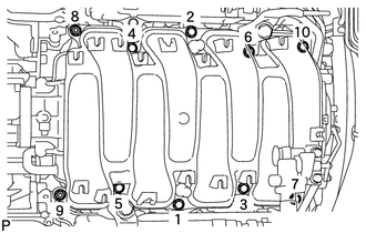
Temporarily install the intake manifold with the 2 nuts and 8 bolts. Then tighten the 2 nuts and 8 bolts uniformly in the order shown in the illustration.
- Torque:
- 21 N*m { 214 kgf*cm, 15 ft.*lbf }
-
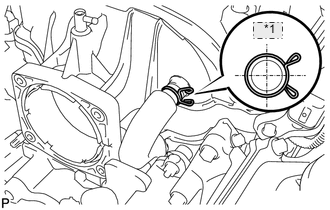
*1 Upper Connect the No. 1 ventilation hose to the intake manifold.
Note
Make sure that the clip is facing as shown in the illustration.
-
-
INSTALL VACUUM SWITCHING VALVE ASSEMBLY
-
Install the vacuum switching valve assembly with the bolt.
- Torque:
- 21 N*m { 214 kgf*cm, 15 ft.*lbf }
-
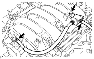
Connect the fuel vapor feed hose to the intake manifold.
-
Connect the No. 2 fuel vapor feed hose to the vacuum switching valve assembly.
-
-
INSTALL WATER BY-PASS PIPE SUB-ASSEMBLY
-
*1 Upper Install the water by-pass pipe sub-assembly to the intake manifold with the 2 bolts.
- Torque:
- 10 N*m { 102 kgf*cm, 7 ft.*lbf }
-
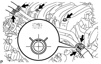
Connect the heater water inlet hose, heater water outlet hose, water inlet hose, and No. 3 water by-pass hose to the water by-pass pipe sub-assembly with the 4 clamps.
Note
Make sure that the No. 3 water by-pass hose clip is facing as shown in the illustration.
-
-
INSTALL INJECTOR DRIVER
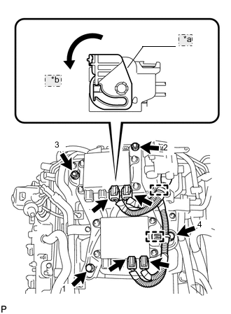
*a Lock Lever *b Move
-
Install the injector driver to the intake manifold by installing the 2 bolts and 2 nuts in the order shown in the illustration.
- Torque:
- 10 N*m { 102 kgf*cm, 7 ft.*lbf }
-
Connect the 4 wire harness connectors to the injector driver. Then move the lock lever as shown in the illustration to lock the connectors.
-
Connect the 2 clamps to the injector driver.
-
-
CONNECT ENGINE WIRE (for LHD)
-
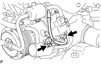
Connect the cooler compressor connector.
-
Connect the wire harness bracket with the bolt.
- Torque:
- 10 N*m { 102 kgf*cm, 7 ft.*lbf }
-
Install the clamp bracket with the bolt.
- Torque:
- 10 N*m { 102 kgf*cm, 7 ft.*lbf }
-
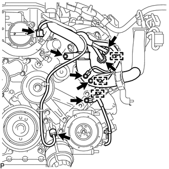
Connect the 3 clamps and 3 ground wires with the 3 bolts.
- Torque:
- 10 N*m { 102 kgf*cm, 7 ft.*lbf }
-
Connect the 2 camshaft timing control motor connectors (for Bank 1).
-
Connect the oil pressure sensor connector.
-
Connect the engine coolant temperature sensor connector.
-
Connect the clamp and install the 2 clamp brackets with the 2 bolts.
- Torque:
- 10 N*m { 102 kgf*cm, 7 ft.*lbf }
-
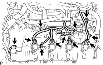
Connect the No. 8 engine wire connector.
-
Connect the fuel pump connector (for high pressure).
-
Connect the 2 VVT sensor connectors.
-
Connect the 4 ignition coil connectors.
-
Connect the camshaft timing control valve connector.
-
for AWD:
-
Connect the engine wire harness with the 4 nuts.
- Torque:
- 10 N*m { 102 kgf*cm, 7 ft.*lbf }
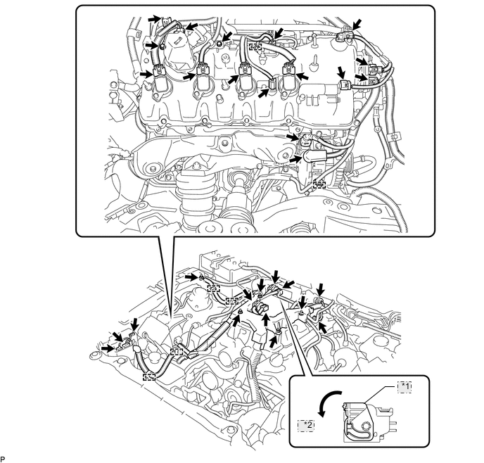
for AWD *1 Lock Lever *2 Move -
Install the 2 engine wire harness clamp brackets with the 2 bolts.
- Torque:
- 10 N*m { 102 kgf*cm, 7 ft.*lbf }
-
Connect the engine wire to the fusible link block assembly with the nut.
- Torque:
- 13 N*m { 127 kgf*cm, 10 ft.*lbf }
-
Connect the engine wire harness to the +B terminal of the generator assembly with the nut.
- Torque:
- 12 N*m { 122 kgf*cm, 9 ft.*lbf }
-
Connect the 6 engine wire harness clamps.
-
Connect the engine wire harness connectors.
Tech Tips
To connect the injector driver connectors, move the lock lever to lock the connector.
-
-
for 2WD:
-
Connect the engine wire harness with the 4 nuts.
- Torque:
- 10 N*m { 102 kgf*cm, 7 ft.*lbf }
for 2WD *1 Lock Lever *2 Move -
Install the 3 engine wire harness clamp brackets with the 3 bolts.
- Torque:
- 10 N*m { 102 kgf*cm, 7 ft.*lbf }
-
Connect the engine wire to the fusible link block assembly with the nut.
- Torque:
- 13 N*m { 127 kgf*cm, 9 ft.*lbf }
-
Connect the engine wire harness to the +B terminal of the generator assembly with the nut.
- Torque:
- 12 N*m { 122 kgf*cm, 9 ft.*lbf }
-
Connect the 7 engine wire harness clamps.
-
Connect the engine wire harness connectors.
Tech Tips
To connect the injector driver connectors, move the lock lever to lock the connector.
-
-
-
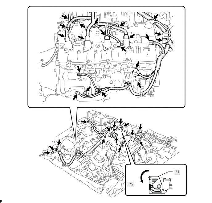
CONNECT ENGINE WIRE (for RHD)
-
Connect the cooler compressor connector.
-
Connect the wire harness bracket with the bolt.
- Torque:
- 10 N*m { 102 kgf*cm, 7 ft.*lbf }
-
Install the clamp bracket with the bolt.
- Torque:
- 10 N*m { 102 kgf*cm, 7 ft.*lbf }
-
Connect the 3 clamps and 3 ground wires with the 3 bolts.
- Torque:
- 10 N*m { 102 kgf*cm, 7 ft.*lbf }
-
Connect the 2 camshaft timing control motor connectors (for Bank 1).
-
Connect the oil pressure sensor connector.
-
Connect the engine coolant temperature sensor connector.
-
Connect the engine wire to the fusible link block assembly with the nut.
- Torque:
- 13 N*m { 127 kgf*cm, 9 ft.*lbf }
-
Attach the 3 wire harness clamps.
-
Connect the clamp and install the 2 clamp brackets with the 2 bolts.
- Torque:
- 10 N*m { 102 kgf*cm, 7 ft.*lbf }
-
Connect the No. 8 engine wire connector.
-
Connect the fuel pump connector (for high pressure).
-
Connect the 2 VVT sensor connectors.
-
Connect the 4 ignition coil connectors.
-
Connect the camshaft timing control valve connector.
-
Connect the engine wire harness with the 4 nuts.
- Torque:
- 10 N*m { 102 kgf*cm, 7 ft.*lbf }
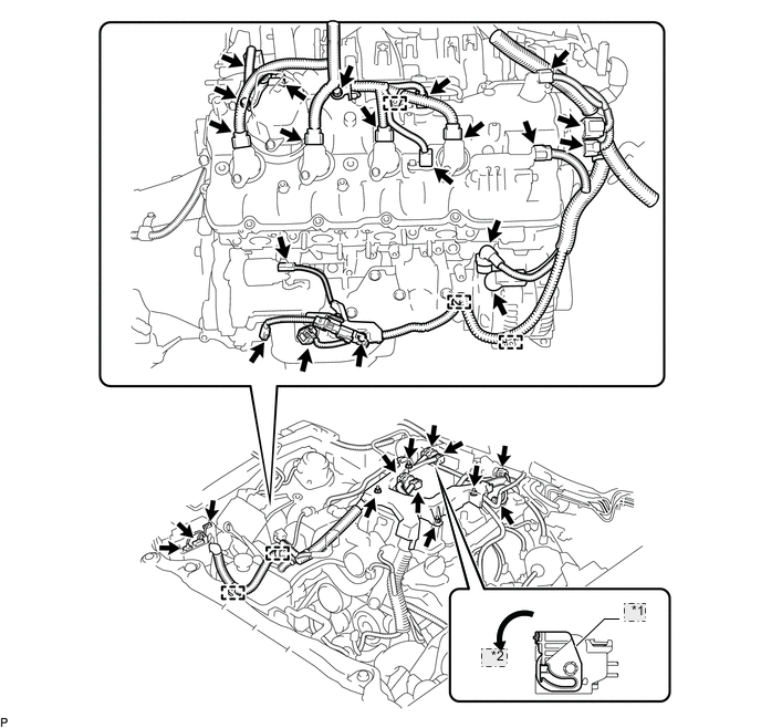
*1 Lock Lever *2 Move -
Install the 3 engine wire harness clamp brackets with the 3 bolts.
- Torque:
- 10 N*m { 102 kgf*cm, 7 ft.*lbf }
-
Connect the 5 engine wire harness clamps.
-
Connect the engine wire harness to the +B terminal of the generator assembly with the nut.
- Torque:
- 12 N*m { 122 kgf*cm, 9 ft.*lbf }
-
Connect the engine wire harness connectors.
Tech Tips
To connect the injector driver connectors, move the lock lever to lock the connector.
-
-
INSTALL NO. 6 ENGINE COVER SUB-ASSEMBLY (for AWD)
-
INSTALL NO. 5 ENGINE COVER SUB-ASSEMBLY (for AWD)
-
INSTALL NO. 2 ENGINE COVER (for LHD with 2WD)
-
INSTALL AIR CLEANER ASSEMBLY LH
-
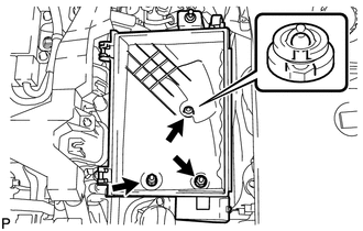
Install the air cleaner case LH with the 2 nuts and clip.
- Torque:
- 5.0 N*m { 51 kgf*cm, 44 in.*lbf }
-
Install the air cleaner filter element to the air cleaner case LH.
-
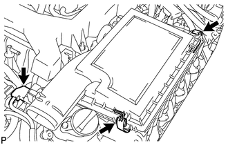
Install the air cleaner cap LH with the 2 clamps.
-
Connect the mass air flow meter connector.
-
-
INSTALL AIR CLEANER ASSEMBLY RH
-
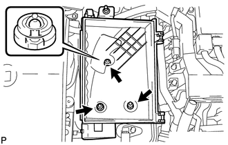
Install the air cleaner case RH with the 2 nuts and clip.
- Torque:
- 5.0 N*m { 51 kgf*cm, 44 in.*lbf }
-
Install the air cleaner filter element to the air cleaner case RH.
-
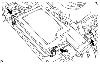
Install the air cleaner cap RH with the 2 clamps.
-
Connect the mass air flow meter connector.
-
-
INSTALL FRONT SUSPENSION MEMBER PROTECTOR LOWER
-
for 2WD: Click here
-
for AWD: Click here
-
-
INSTALL NO. 2 ENGINE UNDER COVER
-
for 2WD: Click here
-
for AWD: Click here
-
-
INSTALL THROTTLE BODY
-
CONNECT CABLE TO NEGATIVE BATTERY TERMINAL
Note
When disconnecting the cable, some systems need to be initialized after the cable is reconnected Click here.
-
INSTALL ENGINE ROOM SIDE COVER RH
-
INSTALL ENGINE ROOM SIDE COVER LH
-
INSTALL COWL TOP VENTILATOR LOUVER