ENGINE(for AWD) REMOVAL

CAUTION / NOTICE / HINT
CAUTION:
As the engine assembly with transmission is extremely heavy, the engine lifter may suddenly drop if the instructions listed in the repair manual are not followed. Therefore, always follow the instructions listed in the repair manual when performing this procedure.
PROCEDURE
-
PLACE FRONT WHEELS FACING STRAIGHT AHEAD
-
RECOVER REFRIGERANT FROM REFRIGERATION SYSTEM
-
DISCHARGE FUEL SYSTEM PRESSURE
-
REMOVE COWL TOP VENTILATOR LOUVER RH
-
PRECAUTION
Note
After turning the engine switch off, waiting time may be required before disconnecting the cable from the battery terminal. Therefore, make sure to read the disconnecting the cable from the battery terminal notice before proceeding with work Click here.
-
DISCONNECT CABLE FROM NEGATIVE BATTERY TERMINAL
CAUTION:
Wait at least 90 seconds after disconnecting the cable from the negative (-) battery terminal to prevent airbag and seat belt pretensioner activation.
Note
When disconnecting the cable, some systems need to be initialized after the cable is reconnected Click here.
-
REMOVE V-BANK COVER SUB-ASSEMBLY
-
REMOVE AIR CLEANER INLET COVER SUB-ASSEMBLY
-
REMOVE NO. 1 AIR CLEANER INLET
-
REMOVE ENGINE ROOM SIDE COVER RH
-
REMOVE ENGINE ROOM SIDE COVER LH
-
REMOVE FRONT CENTER FLOOR COVER
-
Remove the 3 screws, 2 bolts, clip and front center floor cover.
-
-
REMOVE NO. 2 ENGINE UNDER COVER
-
Remove the 4 screws, 2 clips and No. 2 engine under cover.
-
-
REMOVE FRONT WHEEL OPENING EXTENSION PAD LH
-
REMOVE FRONT WHEEL OPENING EXTENSION PAD RH
-
REMOVE NO. 1 ENGINE UNDER COVER
-
REMOVE FRONT SUSPENSION MEMBER PROTECTOR LOWER
-
Remove the 9 bolts and front suspension member protector lower.
-
-
DRAIN ENGINE OIL
-
DRAIN ENGINE COOLANT
-
DRAIN FRONT DIFFERENTIAL OIL
-
DRAIN AUTOMATIC TRANSMISSION FLUID
-
DISCONNECT NO. 1 OIL COOLER INLET HOSE
-
DISCONNECT NO. 1 OIL COOLER OUTLET HOSE
-
REMOVE FRONT BUMPER COVER
-
REMOVE FRONT SUSPENSION LOWER CROSSMEMBER
-
REMOVE REAR FRAME SIDE RAIL
-
Remove the 6 bolts, 4 nuts and 2 rear frame side rails.
-
-
REMOVE INTAKE AIR CONNECTOR PIPE
-
REMOVE AIR CLEANER ASSEMBLY LH
-
REMOVE AIR CLEANER ASSEMBLY RH
-
REMOVE RADIATOR RESERVOIR ASSEMBLY
-
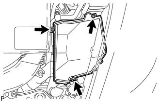
REMOVE ENGINE ROOM ECU OUTLET DUCT
-
Remove the engine room ECU outlet duct from the fan shroud and ECU box.
-
-
DISCONNECT NO. 1 RADIATOR HOSE
-
DISCONNECT NO. 2 RADIATOR HOSE
-
REMOVE RESONATOR BRACKET SUB-ASSEMBLY
-
REMOVE V-RIBBED BELT
-
REMOVE ENGINE OIL PRESSURE SWITCH ASSEMBLY
-
REMOVE OIL TEMPERATURE SENSOR
-
DISCONNECT NO. 3 FUEL HOSE
-
DISCONNECT NO. 1 FUEL PIPE SUB-ASSEMBLY
-
DISCONNECT DISCHARGE HOSE SUB-ASSEMBLY
-
DISCONNECT SUCTION HOSE SUB-ASSEMBLY
-
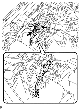
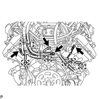
DISCONNECT HOSES AND CONNECTORS
-
Remove the 3 bolts and engine room ECU cover.
-
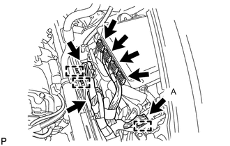
Disconnect the 4 TCM connectors and 2 wiring harness support connectors.
-
Detach the 2 wiring harness support clamps, and then detach the clamp of connector A from the ECU box.
Tech Tips
It is not necessary to disconnect the connection at A in the illustration.
-
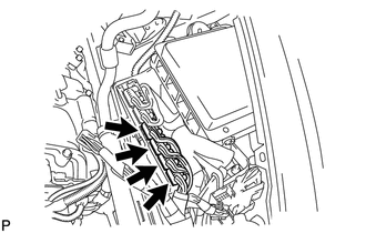
Lift up the wiring harness support and disconnect the 4 ECM connectors.
-
Detach the 2 clamps. Then remove the 2 nuts and disconnect the wires with No. 1 engine room junction block.
-
Detach the clamp and disconnect the 3 connectors with front controller.
-
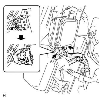
*1 Lock Release the locks of the power steering ECU connector A and disconnect the connectors B.
-
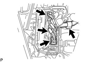
Detach the 2 clamps.
-
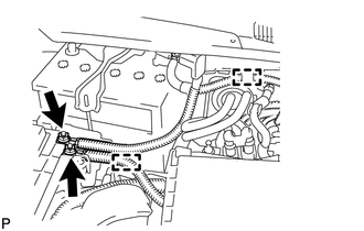
Remove the bolt and disconnect the ground wire.
-
Disconnect the 2 connectors and detach the 5 clamps.
-
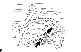
Disconnect the 2 heater hoses.
-
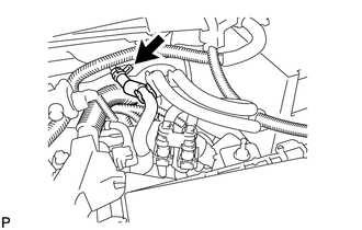
Disconnect the purge line hose.
-
-
REMOVE DRIVER SIDE KNEE AIRBAG ASSEMBLY
-
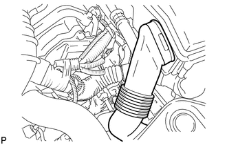
REMOVE NO. 1 AIR DUCT SUB-ASSEMBLY
-
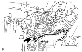
Detach the 2 claws, and remove the bolt and No. 1 air duct sub-assembly.
Note
Be careful not to damage the air duct as its connection to the vehicle is very tight.
-
-
REMOVE NO. 2 STEERING INTERMEDIATE SHAFT ASSEMBLY
-
REMOVE FRONT DRIVE SHAFT ASSEMBLY
-
REMOVE FRONT EXHAUST PIPE ASSEMBLY
-
REMOVE PROPELLER WITH CENTER BEARING SHAFT ASSEMBLY
-
DISCONNECT FLOOR SHIFT GEAR SHIFTING ROD SUB-ASSEMBLY
-
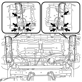
DISCONNECT FRONT LOWER SHOCK ABSORBER BRACKET SUB-ASSEMBLY RH
-
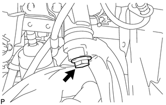
Remove the bolt. Then disconnect the front lower shock absorber bracket sub-assembly RH.
-
-
DISCONNECT FRONT LOWER SHOCK ABSORBER BRACKET SUB-ASSEMBLY LH
-
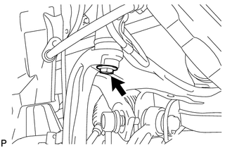
Remove the bolt. Then disconnect the front lower shock absorber bracket sub-assembly LH.
-
-
REMOVE ENGINE AND TRANSMISSION
-
Place a mark (with spray, etc.) over the rear right vehicle side attachment area of the front frame, which is indicated in the illustration.
-
Place a mark (with spray, etc.) over the rear left vehicle side attachment area of the front frame.
-
Set an engine lifter underneath the engine.
Note
-
Place wooden blocks or plate lift attachments so that the engine is level.
-
With the exception of installing the engine assembly to an engine stand or removing the engine assembly from an engine stand, do not perform any work on the engine while it is suspended, as doing so is dangerous.
-
Never install attachments to the oil pan of the engine assembly or transmission as doing so may deform the oil pan.
-
-
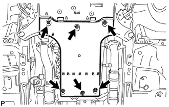
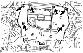
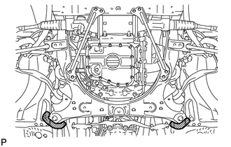
Remove the 4 rear engine mounting member's bolts.
-
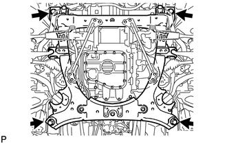
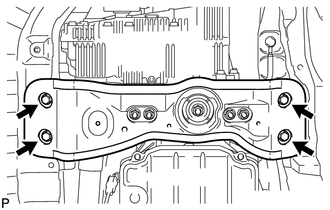
Remove the 4 bolts shown in the illustration.
-
Operate the engine lifter and slowly remove the engine from the vehicle.
Note
-
Make sure that the engine is clear of all wiring and hose.
-
While lowering the engine from the vehicle, do not allow it to contact the vehicle.
-
-
-
INSTALL NO. 1 ENGINE HANGER
-
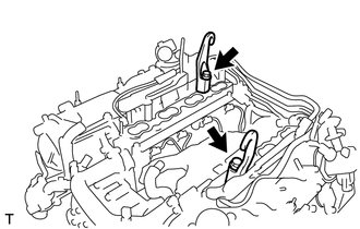
Install the 2 No. 1 engine hangers with the 2 bolts as shown in the illustration.
- Torque:
- 43 N*m { 438 kgf*cm, 32 ft.*lbf }
Tech Tips
No. 1 engine hanger 12281-38150 Bolt 90119-14120 -
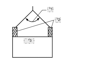
*1 50° or less *2 Engine Hanger *3 ENGINE Attach an engine sling device and hang the engine with a chain block.
Note
When hanging the engine, make sure to hang the engine with the sling device's hanging angle at 50° or less. If not, the engine or No. 1 engine hangers may be damaged.
-
-
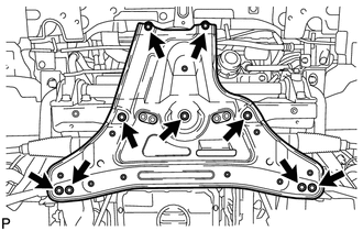
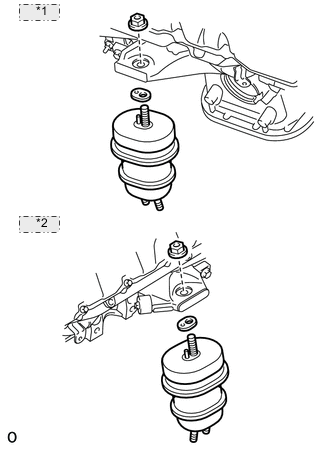
REMOVE FRONT FRAME ASSEMBLY
-
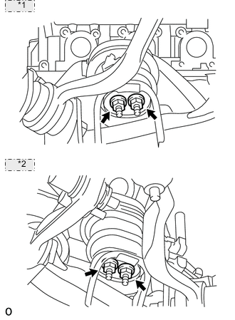
*1 for RH: *2 for LH: Remove the 4 nuts and front frame assembly.
-
-
REMOVE ENGINE OIL LEVEL DIPSTICK GUIDE
-
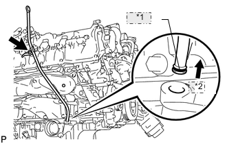
*1 O-Ring *2 Pull Remove the engine oil level dipstick.
-
Remove the 2 bolts and engine oil level dipstick guide.
-
Remove the O-ring from the engine oil level dipstick guide.
-
-
REMOVE GENERATOR ASSEMBLY
-
REMOVE NO. 1 EXHAUST MANIFOLD HEAT INSULATOR
-
REMOVE NO. 2 EXHAUST MANIFOLD HEAT INSULATOR
-
REMOVE FRONT ENGINE MOUNTING INSULATOR
-
*1 for RH: *2 for LH: Remove the 2 nuts, 2 engine mounting spacers and 2 front engine mounting insulators.
-
-
REMOVE FRONT NO. 1 ENGINE MOUNTING BRACKET RH
-
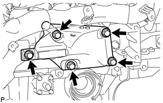
Remove the 5 bolts and front No. 1 engine mounting bracket RH.
-
-
REMOVE FRONT NO. 1 ENGINE MOUNTING BRACKET LH
-
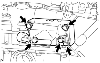
Remove the 5 bolts and front No. 1 engine mounting bracket LH.
-
-
REMOVE EXHAUST MANIFOLD SUB-ASSEMBLY RH
-
REMOVE EXHAUST MANIFOLD SUB-ASSEMBLY LH
-
REMOVE FRONT NO. 2 ENGINE MOUNTING BRACKET RH
-
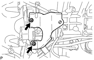
Remove the 2 nuts and front No. 2 engine mounting bracket RH.
-
-
REMOVE FRONT NO. 2 ENGINE MOUNTING BRACKET LH
-
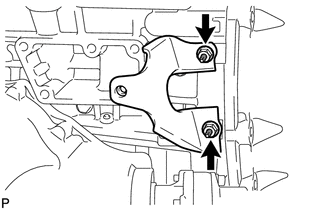
Remove the 2 nuts and front No. 2 engine mounting bracket LH.
-
-
REMOVE NO. 3 EXHAUST MANIFOLD HEAT INSULATOR
-
REMOVE STARTER ASSEMBLY
-
REMOVE FRONT PROPELLER SHAFT ASSEMBLY
-
REMOVE NO. 1 OIL COOLER TUBE
-
REMOVE NO. 3 COVER SUB-ASSEMBLY
-
DISCONNECT WIRE HARNESS AND CONNECTOR
-
REMOVE DRIVE PLATE AND TORQUE CONVERTER SETTING BOLT
-
REMOVE AUTOMATIC TRANSMISSION ASSEMBLY
-
REMOVE DRIVE PLATE AND RING GEAR SUB-ASSEMBLY
-
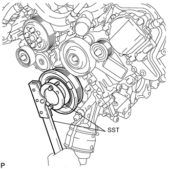
Using SST, hold the crankshaft.
- SST
- 09213-54015 ( 90119-08216 )
- 09330-00021
-
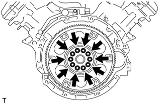
Remove the 10 bolts, rear spacer plate, drive plate and ring gear sub-assembly and crankshaft position sensor rotor.
-
-
INSTALL ENGINE ON ENGINE STAND
-
Install the engine onto an engine stand with the bolts.
Note
-
Pay attention to the angle of the sling device as the engine assembly or No. 1 engine hangers may be damaged or deformed if the angle is incorrect.
-
With the exception of installing the engine assembly to an engine stand or removing the engine assembly from an engine stand, do not perform any work on the engine while it is suspended, as doing so is dangerous.
-
-
Remove the 2 bolts and 2 No. 1 engine hangers.
-
-
REMOVE COOLER COMPRESSOR ASSEMBLY
-
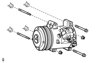
Remove the 2 bolts, 2 nuts, 2 stud bolts and cooler compressor assembly.
-
-
REMOVE FRONT DIFFERENTIAL CARRIER ASSEMBLY
-
REMOVE NO. 5 ENGINE COVER SUB-ASSEMBLY
-
REMOVE NO. 6 ENGINE COVER SUB-ASSEMBLY
-
REMOVE ENGINE WIRE
-
for Engine LH Side:
-
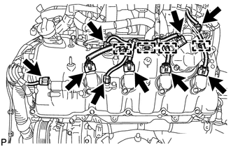
Disconnect the camshaft timing control valve connector.
-
Disconnect the 4 ignition coil connectors.
-
Disconnect the 2 VVT sensor connectors.
-
Disconnect the fuel pump connector (for high pressure).
-
Disconnect the No. 8 engine wire connector.
-
Disconnect the 4 wire harness clamps.
-
-
for Engine Front Side:
-
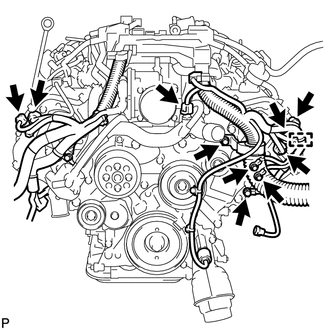
Disconnect the engine coolant temperature sensor connector.
-
Disconnect the 2 camshaft timing control motor connectors (for Bank 1).
-
Disconnect the 2 camshaft timing control motor connectors (for Bank 2).
-
Remove the 3 bolts and disconnect the clamp and ground wire.
-
Remove the bolt and clamp bracket.
-
-
for Engine RH Side:
-
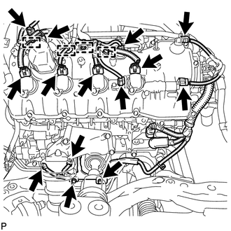
Disconnect the camshaft timing control valve connector.
-
Disconnect the 4 ignition coil connectors.
-
Disconnect the 2 VVT sensor connectors.
-
Disconnect the fuel pump connector (for high pressure).
-
Disconnect the camshaft position sensor connector.
-
Detach the 4 wire harness clamps.
-
Disconnect the crankshaft position sensor connector.
-
Remove the 2 bolts and disconnect the engine oil level sensor connector.
-
-
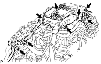
for Engine Rear Side:
-
Disconnect the engine wire connector.
-
Disconnect the fuel relief valve connector.
-
Detach the 8 wire harness clamps.
-
Remove the 2 bolts and disconnect the ground wire.
-
-
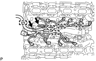
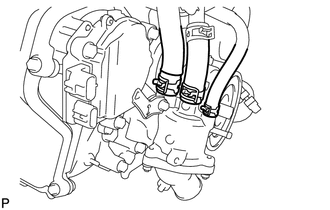
Disconnect the throttle body connector.
-
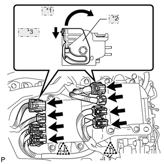
*1 Move *2 Lock Lever *3 Release Disconnect the 8 injector driver connectors and detach the 2 clips as shown in the illustration.
-
Disconnect the purge VSV connector.
-
Disconnect the intake air control valve actuator connector.
-
Remove the 2 bolts and disconnect the 2 clamp brackets and 2 clamps.
-
Remove the 4 nuts and engine wire.
-
-
REMOVE INJECTOR DRIVER
-
REMOVE NO. 1 ENGINE COVER
-
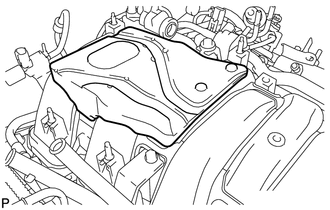
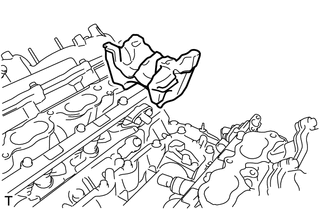
Remove the No. 1 engine cover.
-
-
REMOVE WATER BY-PASS PIPE SUB-ASSEMBLY
-
REMOVE PURGE VSV
-
REMOVE VENTILATION HOSE
-
REMOVE THROTTLE BODY ASSEMBLY
-
REMOVE INTAKE MANIFOLD
-
REMOVE FUEL TUBE SUB-ASSEMBLY
-
REMOVE FUEL PRESSURE PULSATION DAMPER ASSEMBLY
-
REMOVE NO. 3 FUEL PIPE SUB-ASSEMBLY
-
REMOVE NO. 2 FUEL PIPE SUB-ASSEMBLY
-
REMOVE ENGINE COVER SUB-ASSEMBLY (for Bank 1)
-
REMOVE ENGINE COVER SUB-ASSEMBLY (for Bank 2)
-
REMOVE FUEL PUMP ASSEMBLY (for Bank 1)
-
REMOVE FUEL PUMP ASSEMBLY (for Bank 2)
-
REMOVE FUEL DELIVERY PIPE (for Port Injection)
-
REMOVE FUEL INJECTOR ASSEMBLY (for Port Injection)
-
REMOVE NO. 1 ENGINE COVER SUB-ASSEMBLY
-
REMOVE NO. 2 ENGINE COVER SUB-ASSEMBLY
-
REMOVE NO. 2 ENGINE COVER SUB-ASSEMBLY LH
-
REMOVE NO. 4 FUEL PIPE SUB-ASSEMBLY
-
REMOVE FUEL DELIVERY PIPE (for Direct Injection)
-
REMOVE NO. 2 FUEL DELIVERY PIPE (for Direct Injection)
-
REMOVE FUEL INJECTOR ASSEMBLY (for Direct Injection)
-
REMOVE FUEL INJECTOR SEAL (for Direct Injection)
-
REMOVE SEPARATOR CASE
-
REMOVE ENGINE WIRE
-
Detach the 5 clamps and remove the 2 bolts and engine wire.
-
Disconnect the 4 knock sensor connectors.
-
-
REMOVE NO. 4 ENGINE COVER SUB-ASSEMBLY
-
Remove the No. 4 engine cover sub-assembly.
-
-
REMOVE KNOCK SENSOR
-
REMOVE NO. 2 IDLER PULLEY SUB-ASSEMBLY
-
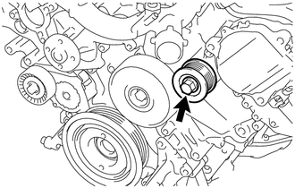
Remove the bolt and No. 2 idler pulley sub-assembly.
-
-
REMOVE NO. 1 IDLER PULLEY SUB-ASSEMBLY
-
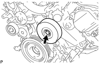
Remove the bolt and No. 1 idler pulley sub-assembly.
-
-
REMOVE WATER PUMP PULLEY
-
REMOVE WATER INLET HOUSING
-
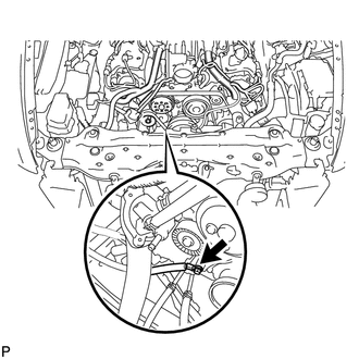
Using needle-nose pliers, grip the claws of the clip and slide the clip to disconnect the water by-pass hose and water inlet hose.
-
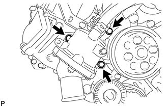
Remove the 3 bolts, water inlet housing and gasket.
-
-
REMOVE ENGINE OIL LEVEL SENSOR
-
REMOVE ENGINE COOLANT TEMPERATURE SENSOR
-
REMOVE IGNITION COIL ASSEMBLY