АВТОМАТИЧЕСКАЯ ТРАНСМИССИЯ В СБОРЕ (для моделей с 2KD-FTV) УСТАНОВКА

-
INSTALL TORQUE CONVERTER ASSEMBLY
-
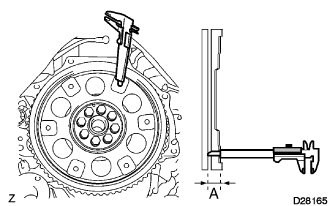
Using vernier calipers, measure the dimension A between the transmission and the end of surface of drive plate.
-
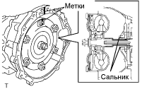
Aligning the matchmarks on the transmission case and torque converter assembly , engage the spline of the input shaft and turbine runner.
Note
Install the torque converter assembly to the input shaft in horizontally.
-
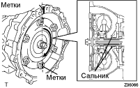
Engage the spline of the stator shaft and stator while turning the torque converter assembly to a clockwise.
Note
-
Turn the torque converter assembly approximately 180°.
-
Be sure not to damage the oil seal.
-
Install the torque converter assembly to the input shaft in horizontally.
-
-
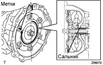
Turn the torque converter assembly to the clockwise and align the matchmarks on the torque converter assembly and gear into the slot on the torque converter assembly.
Note
Do not push on the torque converter assembly when aligning the matchmarks.
-
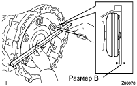
Using calipers and straight edge , measure the dimension B shown in the illustration and check that B is greater than A measured in step (a).
Standard Dimension B = A + 1 mm (0.04 in.) or more
-
-
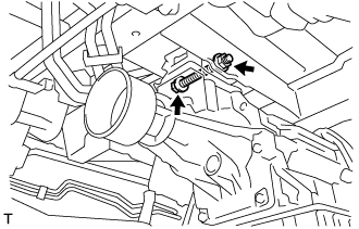
INSTALL BREATHER PLUG HOSE
-
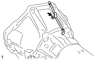
Install the breather plug hose to the automatic transmission assembly with the bolt.
- Torque:
- 7.5 N*m { 75 kgf*cm, 65 in.*lbf }
-
-
INSTALL ENGINE MOUNTING INSULATOR ASSEMBLY REAR
-
Install the engine mounting insulator assembly rear with the 4 bolts.
- Torque:
- 29 N*m { 296 kgf*cm, 21 ft.*lbf }
-
-
INSTALL TRANSMISSION CONTROL CABLE BRACKET NO.1
-
Install the transmission control cable bracket No.1 to the automatic transmission assembly with the 2 bolts.
- Torque:
- 28 N*m { 286 kgf*cm, 21 ft.*lbf }
-
-
INSTALL AUTOMATIC TRANSMISSION ASSEMBLY
-
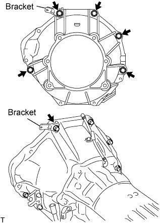
Install the automatic transmission assembly with the 5 bolts.
- Torque:
- 71 N*m { 724 kgf*cm, 52 ft.*lbf }
Tech Tips
Install the bolt so that the bracket is tighten as shown in the illustration.
-
-
INSTALL ENGINE MOUNTING INSULATOR ASSEMBLY REAR
-
Install the engine mounting insulator assembly rear with the bolt, nut and washer.
- Torque:
- 98 N*m { 999 kgf*cm, 72 ft.*lbf }
Tech Tips
Put a washer both side of the bolt and nut.
-
-
INSTALL DRIVE PLATE AND TORQUE CONVERTER CLUTCH SETTING BOLT
-
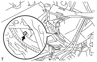
Turn the crankshaft pulley and install the 6 torque converter clutch setting bolts.
- Torque:
- 41 N*m { 420 kgf*cm, 30 ft.*lbf }
Tech Tips
First install the matchmarks bolt (Black painted).
-
Install the drive plate cover to the automatic transmission assembly with the bolt.
- Torque:
- 73 N*m { 744 kgf*cm, 54 ft.*lbf }
-
-
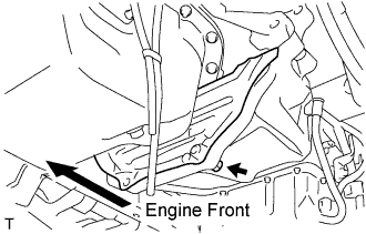
INSTALL STIFFENER PLATE RH(ATM)
-
Install the stiffener plate RH with the 3 bolts.
- Torque:
- 71 N*m { 724 kgf*cm, 52 ft.*lbf }
Tech Tips
Install the bolt so that the bracket is tighten as shown in the illustration.
-
-
INSTALL CYLINDER BLOCK INSULATOR NO.4
-
Install the cylinder block insulator.
-
-
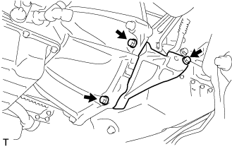
INSTALL WIRE HARNESS
-
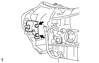
Install the wire harness to the automatic transmission assembly with the 2 bolts.
- Torque:
- 5.4 N*m { 55 kgf*cm, 47 in.*lbf }
-
-
INSTALL CONNECTOR
-
w/ Speedometer Sensor:
-
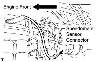
Connect the speedometer sensor connector.
-
-
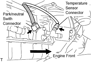
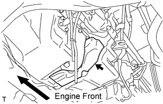
Connect the park/neutral switch connector and the temperature sensor connector.
-
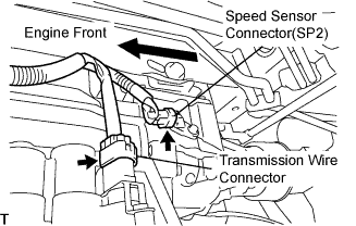
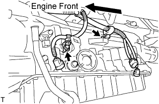
Connect the speed sensor connector (SP2) and the transmission wire connector.
-
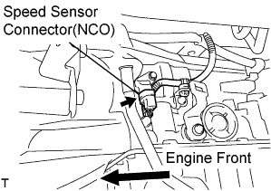
Connect the speed sensor connector (NCO).
-
-
INSTALL OIL COOLER TUBE
-
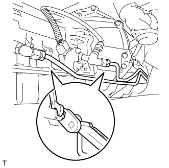
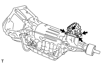
Using a 17 mm union nut wrench, install the 2 oil cooler tubes to the automatic transmission assembly.
- Torque:
- 34 N*m { 347 kgf*cm, 25 ft.*lbf }
Note
Use the formula to calculate special torque values for situations where a union nut wrench is combined with a torque wrench Click here.
-
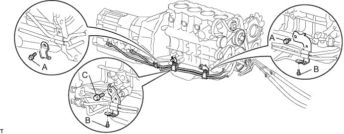
Install the 3 oil cooler tube clamps with the 5 bolts.
- Torque:
- for Bolt A
- 12 N*m { 122 kgf*cm, 8 ft.*lbf }
- for Bolt B
- 5.0 N*m { 51 kgf*cm, 44 in.*lbf }
- for Bolt C
- 71 N*m { 724 kgf*cm, 52 ft.*lbf }
-
-
INSTALL TRANSMISSION CONTROL CABLE ASSEMBLY
-
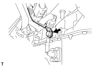
Fix the transmission control cable assembly to the control cable bracket with a clip.
-
Install the transmission control cable assembly to the control shaft lever with the nut.
- Torque:
- 15 N*m { 150 kgf*cm, 11 ft.*lbf }
-
-
INSTALL TRANSMISSION OIL FILLER TUBE SUB-ASSEMBLY
-
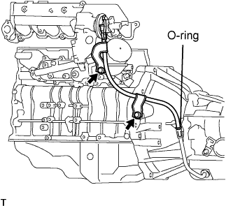
Coat a new O-ring with ATF and install the oil filler tube.
-
Install the oil filler tube with the 2 bolts.
- Torque:
- 12 N*m { 122 kgf*cm, 8 ft.*lbf }
-
-
INSTALL STARTER ASSEMBLY
-
Install the starter with the bolt and 2 nuts.
- Torque:
- 68 N*m { 693 kgf*cm, 50 ft.*lbf }
-
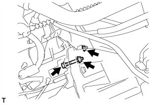
Connect the wire harness to terminal 30 and install the nut.
- Torque:
- 21 N*m { 215 kgf*cm, 16 ft.*lbf }
-
Close the terminal cap.
-
Connect the terminal 50 connector to the starter assembly.
-
for Wide Body:
Install the wire ground cable with the bolt.
- Torque:
- 25 N*m { 250 kgf*cm, 18 ft.*lbf }
-
-
INSTALL EXHAUST PIPE ASSEMBLY FRONT
-
Установите пружину сжатия.
-
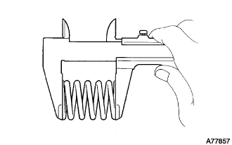
С помощью штангенциркуля измерьте длину пружин в свободном состоянии.
Минимально допустимая длина 40,5 мм (1,594 дюйма) Tech Tips
Если длина в свободном состоянии меньше минимально допустимой, замените пружину сжатия.
-
-
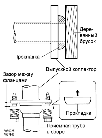
Установите прокладку.
-
Полностью вставьте рукой новую прокладку в выпускной коллектор.
-
Наденьте прокладку на выпускной коллектор с помощью деревянного бруска, равномерно распределяя удары.
Note
-
Правильно выберите направление установки прокладки.
-
Повторное использование прокладок запрещено.
-
Действуйте осторожно, чтобы не повредить прокладку.
-
Чтобы обеспечить хорошее уплотнение, не насаживайте прокладку на выпускной коллектор с помощью приемной трубы.
-
-
-
Подсоедините опору выпускной трубы, установите приемную трубу в сборе и закрепите ее 4 болтами, 2 пружинами сжатия и 2 гайками.
- Torque:
- со стороны выпускного коллектора
- 43 Н*м { 438 кгс*см, 32 фунт-сила-фута }
- со стороны приемной трубы в сборе
- 48 Н*м { 489 кгс*см, 35 фунт-сила-футов }
Note
После установки убедитесь, что зазор между фланцами выпускного коллектора и приемной трубы приблизительно одинаков по всему периметру.
-
-
INSTALL PROPELLER SHAFT ASSEMBLY
-
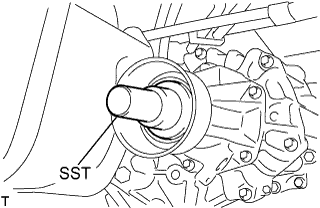
Снимите SST с удлинителя картера трансмиссии.
-
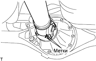
Установите карданный вал в сборе в удлинитель картера трансмиссии.
-
Совместите метки на фланце карданного вала и фланце дифференциала.
-
Закрепите карданный вал в сборе с помощью 4 гаек, 4 болтов и 4 шайб.
- Torque:
- 74 Н*м { 755 кгс*см, 54 фунт-сила-фута }
-
-
INSTALL ENGINE UNDER COVER SUB-ASSEMBLY NO.2
- Torque:
- 13 N*m { 133 kgf*cm, 10 ft.*lbf }
-
INSTALL ENGINE UNDER COVER NO.1
- Torque:
- 13 N*m { 133 kgf*cm, 10 ft.*lbf }
-
CONNECT BATTERY NEGATIVE CABLE
-
ADD AUTOMATIC TRANSMISSION FLUID
-
INSPECT AUTOMATIC TRANSMISSION FLUID
Tech Tips
Совершите поездку на автомобиле с тем, чтобы двигатель и трансмиссия прогрелись до нормальной рабочей температуры.
Температура жидкости 70 - 80 °C (158 - 176 °F)
-
Установите автомобиль на ровную поверхность и включите стояночный тормоз.
-
При работающем на холостом ходу двигателе и нажатой педали тормоза установите рычаг переключения передач во все положения от P до L, а затем верните его в положение P.
-
Вытащите щуп и вытрите его насухо.
-
Вставьте его обратно до упора.
-
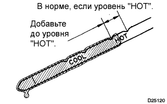
Извлеките его снова и убедитесь, что уровень жидкости попадает в диапазон НОТ.
Если уровень жидкости не доходит до диапазона HOT, добавьте новую жидкость и проверьте уровень повторно. Если уровень жидкости выходит за верхний предел диапазона HOT, однократно слейте жидкость, добавьте необходимое количество новой жидкости и проверьте уровень повторно.
-
-
INSPECT SHIFT LEVER POSITION
-
Переключая передачу только из положения P при включенном зажигании, нажмите педаль тормоза.
-
Убедитесь, что рычаг переключения передач движется плавно и перемещается под умеренным усилием.
-
Запустив двигатель, убедитесь, что при переключении рычага из положения N в положение D автомобиль двигается вперед, а при переключении в положение R - назад.
-
-
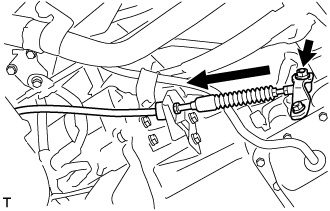
ADJUST SHIFT LEVER POSITION
-
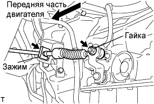
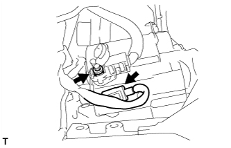
Снимите фиксатор, отверните гайку и отсоедините трос механизма переключения передач в сборе от рычага приводного вала и кронштейна троса механизма переключения передач № 1.
-
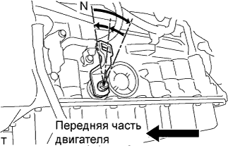
Поверните рычаг приводного вала до упора по часовой стрелке, а затем верните его на 2 метки в обратном направлении в положение N.
-
Установите рычаг переключения передач в положение N, слегка нажимая на него в направлении положения R, и установите его.
- Torque:
- 15 Н*м { 150 кгс*см, 11 фунт-сила-футов }
Note
Затяните гайку, чтобы исключить смешение деталей.
-
Проверьте режим работы и правильность работы.
-
-
CHECK EXHAUST GAS LEAKS
-
PERFORM INITIALIZATION