SMART ENTRY AND START SYSTEM (for Entry Function) Front Passenger Side Door Entry Unlock Function does not Operate
DESCRIPTION
If the entry unlock function does not operate for the front passenger door only, but the entry lock function operates, the request code is being transmitted properly from the front passenger door. In this case, there may be a problem related to the except driver door lock position switch system.
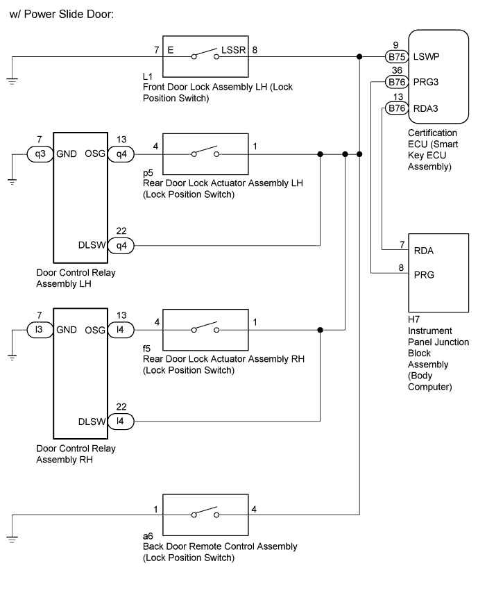
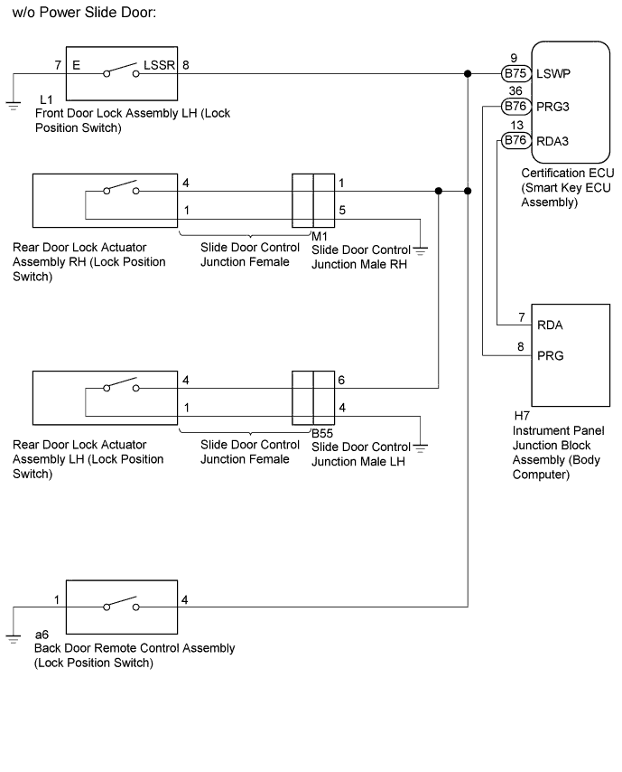
WIRING DIAGRAM
INSPECTION PROCEDURE
Note
-
The smart entry and start system (for Entry Function) uses a multiplex communication system (LIN communication system) and the CAN communication system. Inspect the communication function by following How to Proceed with Troubleshooting Click here. Troubleshoot the smart entry and start system (for Entry Function) after confirming that the communication systems are functioning properly.
-
When using the GTS with the vehicle engine switch off, connect the GTS to the vehicle and turn a courtesy light switch on and off at intervals of 1.5 seconds or less until communication between the GTS and the vehicle begins. Then select the Model Code "KEY REGIST" under manual mode and enter the following menus: Body Electrical / Entry&Start(CAN).
While using the GTS, periodically turn a courtesy light switch on and off at intervals of 1.5 seconds or less to maintain communication between the GTS and the vehicle.
-
Check that there are no electrical key transmitter sub-assemblies in the vehicle.
-
Before performing the inspection, check that DTC B1242 (wireless door lock control) or B27B0 is not output.
-
Before replacing the certification ECU (smart key ECU assembly), refer to the smart entry and start system (for Entry Function) precaution Click here.
-
After repair, confirm that no DTCs are output by performing the "DTC Output Confirmation Operation".
PROCEDURE
-
CHECK POWER DOOR LOCK CONTROL SYSTEM
-
When the door control switch on the power window regulator master switch assembly is operated, check that the doors unlock and lock according to the switch operation Click here.
OK Door locks operate normally.
NG 
GO TO POWER DOOR LOCK CONTROL SYSTEM Click here
OK 
-
-
INSPECT DOOR LOCK POSITION SWITCH
-
Remove the front door lock assembly LH (lock position switch) Click here.
-
Remove the rear door lock actuator assembly RH/LH (lock position switch) Click here.
-
Remove the back door remote control assembly (lock position switch) Click here.
-
Inspect the front door lock assembly LH (lock position switch) Click here.
-
Inspect the rear door lock actuator assembly RH (lock position switch) Click here.
-
Inspect the rear door lock actuator assembly LH (lock position switch) Click here.
-
Inspect the back door remote control assembly (lock position switch) Click here.
Result Result Proceed to OK (w/ Power Slide Door) A OK (w/o Power Slide Door) B NG C
B 
CHECK HARNESS AND CONNECTOR (LOCK POSITION SWITCH CIRCUIT) Click here
C
REPLACE TROUBLE PARTS
A
-
-
CHECK HARNESS AND CONNECTOR (LOCK POSITION SWITCH CIRCUIT)
-
Disconnect the B75 certification ECU (smart key ECU assembly) connector.
-
Disconnect the L1 front door lock assembly LH connector.
-
Disconnect the p5 rear door lock actuator assembly LH connector.
-
Disconnect the q4 and q3 door control relay assembly LH connectors.
-
Disconnect the f5 rear door lock actuator assembly RH connector.
-
Disconnect the l4 and l3 door control relay assembly RH connectors.
-
Disconnect the a6 back door remote control assembly connector.
-
Measure the resistance according to the value(s) in the table below.
Standard Resistance Tester Connection Condition Specified Condition B75-9 (LSWP) - L1-8 (LSSR) Always Below 1 Ω B75-9 (LSWP) - p5-1 Always Below 1 Ω B75-9 (LSWP) - q4-22 (DLSW) Always Below 1 Ω B75-9 (LSWP) - f5-1 Always Below 1 Ω B75-9 (LSWP) - l4-22 (DLSW) Always Below 1 Ω B75-9 (LSWP) - a6-4 Always Below 1 Ω L1-7 (E) - Body ground Always Below 1 Ω p5-4 - q4-13 (OSG) Always Below 1 Ω q3-7 (GND) - Body ground Always Below 1 Ω f5-4 - l4-13 (OSG) Always Below 1 Ω l3-7 (GND) - Body ground Always Below 1 Ω a6-1 - Body ground Always Below 1 Ω B75-9 (LSWP) or L1-8 (LSSR) - Body ground Always 10 kΩ or higher B75-9 (LSWP) or p5-1 - Body ground Always 10 kΩ or higher B75-9 (LSWP) or q4-22 (DLSW) - Body ground Always 10 kΩ or higher p5-4 or q4-13 (OSG) - Body ground Always 10 kΩ or higher B75-9 (LSWP) or f5-1 - Body ground Always 10 kΩ or higher B75-9 (LSWP) or l4-22 (DLSW) - Body ground Always 10 kΩ or higher f5-4 or l4-13 (OSG) - Body ground Always 10 kΩ or higher B75-9 (LSWP) or a6-4 - Body ground Always 10 kΩ or higher
NG
REPAIR OR REPLACE HARNESS OR CONNECTOR
OK
-
-
CHECK ENTRY DOOR LOCK OPERATION
-
Check the entry lock/unlock operation.
OK Entry lock/unlock operate normally.
NG
REPLACE DOOR CONTROL RELAY ASSEMBLY Click here
OK 
END (CONNECTOR WAS NOT CONNECTED PROPERLY)
-
-
REPLACE DOOR CONTROL RELAY ASSEMBLY
-
Replace a new door control relay assembly Click here.
NEXT
-
-
CHECK ENTRY DOOR LOCK OPERATION
-
Check the entry lock/unlock operation.
OK Entry lock/unlock operate normally.
NG
REPLACE INSTRUMENT PANEL JUNCTION BLOCK ASSEMBLY (BODY COMPUTER) Click here
OK
END (DOOR CONTROL RELAY ASSEMBLY WAS DEFECTIVE)
-
-
CHECK HARNESS AND CONNECTOR (LOCK POSITION SWITCH CIRCUIT)
-
Disconnect the B75 certification ECU (smart key ECU assembly) connector.
-
Disconnect the L1 front door lock assembly LH connector.
-
Disconnect the M1 slide door control junction male RH connector.
-
Disconnect the B55 slide door control junction male LH connector.
-
Disconnect the a6 back door remote control assembly connector.
-
Measure the resistance according to the value(s) in the table below.
Standard Resistance Tester Connection Condition Specified Condition B75-9 (LSWP) - L1-8 (LSSR) Always Below 1 Ω B75-9 (LSWP) - M1-1 Always Below 1 Ω B75-9 (LSWP) - B55-6 Always Below 1 Ω B75-9 (LSWP) - a6-4 Always Below 1 Ω L1-7 (E) - Body ground Always Below 1 Ω M1-5 - Body ground Always Below 1 Ω B55-4 - Body ground Always Below 1 Ω a6-1 - Body ground Always Below 1 Ω B75-9 (LSWP) or L1-8 (LSSR) - Body ground Always 10 kΩ or higher B75-9 (LSWP) or M1-1 - Body ground Always 10 kΩ or higher B75-9 (LSWP) or B55-6 - Body ground Always 10 kΩ or higher B75-9 (LSWP) or a6-4 - Body ground Always 10 kΩ or higher
NG
REPAIR OR REPLACE HARNESS AND CONNECTOR
OK
-
-
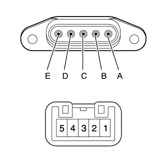
INSPECT SLIDE DOOR CONTROL JUNCTION FEMALE
-
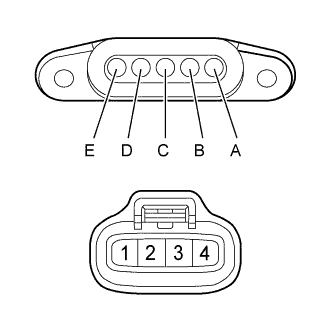
Remove the slide door control junction female.
-
Measure the resistance according to the value(s) in the table below.
Standard Resistance Tester Connection Condition Specified Condition A - 2 Always Below 1 Ω B - 1 Always Below 1 Ω C - 4 Always Below 1 Ω E - 3 Always Below 1 Ω
NG
REPLACE SLIDE DOOR CONTROL JUNCTION FEMALE
OK
-
-
INSPECT SLIDE DOOR CONTROL JUNCTION MALE
-
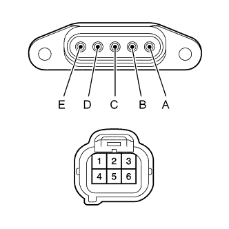
Remove the slide door control junction male LH.
-
Measure the resistance according to the value(s) in the table below.
Standard Resistance Tester Connection Condition Specified Condition A - 5 Always Below 1 Ω B - 1 Always Below 1 Ω C - 6 Always Below 1 Ω D - 4 Always Below 1 Ω E - 2 Always Below 1 Ω -
Remove the slide door control junction male RH.
-
Measure the resistance according to the value(s) in the table below.
Standard Resistance Tester Connection Condition Specified Condition A - 2 Always Below 1 Ω B - 5 Always Below 1 Ω C - 1 Always Below 1 Ω D - 4 Always Below 1 Ω E - 3 Always Below 1 Ω
NG
REPLACE SLIDE DOOR CONTROL JUNCTION MALE
OK
-
-
CHECK ENTRY DOOR LOCK OPERATION
-
Check the entry lock/unlock operation.
OK Entry lock/unlock operate normally.
NG
REPLACE INSTRUMENT PANEL JUNCTION BLOCK ASSEMBLY (BODY COMPUTER) Click here
OK
END (CONNECTOR WAS NOT CONNECTED PROPERLY)
-
-
REPLACE INSTRUMENT PANEL JUNCTION BLOCK ASSEMBLY (BODY COMPUTER)
-
Replace the instrument panel junction block assembly (body computer) with a new or known good one.
NEXT
-
-
CHECK ENTRY DOOR LOCK OPERATION
-
Check the entry lock/unlock operation.
OK Entry lock/unlock operate normally.
NG
REPLACE CERTIFICATION ECU (SMART KEY ECU ASSEMBLY)
OK
END (INSTRUMENT PANEL JUNCTION BLOCK ASSEMBLY [BODY COMPUTER] WAS DEFECTIVE)
-