SPIRAL CABLE REMOVAL

-
PRECAUTION
CAUTION:
Be sure to read Precaution thoroughly before servicing Click here.
Note
After turning the ignition switch off, waiting time may be required before disconnecting the cable from the battery terminal. Therefore, make sure to read the disconnecting the cable from the battery terminal notice before proceeding with work Click here.
-
PLACE FRONT WHEELS FACING STRAIGHT AHEAD
-
DISCONNECT CABLE FROM NEGATIVE BATTERY TERMINAL
CAUTION:
Wait at least 90 seconds after disconnecting the cable from the negative (-) battery terminal to disable the SRS system.
Note
When disconnecting the cable, some systems need to be initialized after the cable is reconnected Click here.
-
REMOVE STEERING PAD
-
REMOVE STEERING WHEEL ASSEMBLY
-
Remove the steering wheel set nut.
-
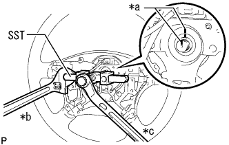
Text in Illustration *a Matchmark *b Hold *c Turn Put matchmarks on the steering wheel assembly and steering main shaft assembly.
-
Using SST, remove the steering wheel assembly.
- SST
- 09950-50013 ( 09951-05010, 09952-05010, 09953-05020, 09954-05021 )
Note
Apply a small amount of grease to the threads and tip of SST (09953-05020) before use.
-
-
REMOVE NO. 2 STEERING COLUMN LOWER COVER (w/ Smart Entry and Start System)
-
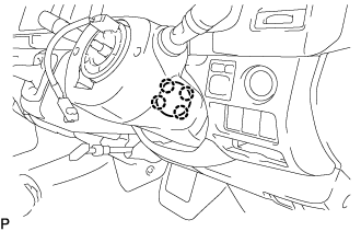
Detach the 4 claws and remove the No. 2 steering column lower cover.
-
-
REMOVE LOWER STEERING COLUMN COVER
Tech Tips
Adjust the position of the steering tilt mechanism when performing the procedure.
-
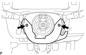
Remove the 2 "TORX" screws (T25) from the steering column lower cover.
-
Push the steering column lower cover inward on both sides to detach the 2 claws.
-
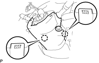
Detach the 2 claws and remove the steering column lower cover.
-
-
REMOVE COMBINATION METER ASSEMBLY
-
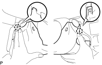
REMOVE UPPER STEERING COLUMN COVER
-
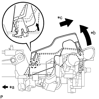
Text in Illustration *a Front of Vehicle *b Raise the backside of the steering column upper cover *c Pull diagonally backwards so that the claw of the steering column upper cover does not break Remove the steering column upper cover from the steering column assembly.
Note
If the steering column upper cover is removed by pulling it directly upwards, the claw may become damaged.
-
-
REMOVE SPIRAL CABLE SUB-ASSEMBLY
Note
-
Do not replace the spiral cable sub-assembly with the battery connected and the ignition switch ON.
-
Do not rotate the spiral cable sub-assembly with the battery connected and the ignition switch ON.
-
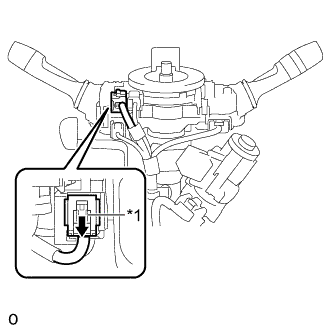
Text in Illustration *1 Slider Slide the slider to release the lock, and then disconnect the yellow airbag connector from the spiral cable sub-assembly.
Note
When disconnecting any airbag connector, take care not to damage the airbag wire harness.
-
Disconnect the connector from the spiral cable sub-assembly.
-
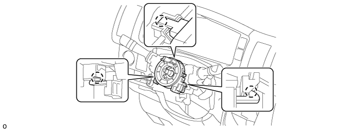
Detach the 3 claws and remove the spiral cable sub-assembly.
-
-
REMOVE SPIRAL CABLE (w/ VSC)
Note
-
Remove the spiral cable from the steering sensor only when replacing it.
-
Install the lock pin to the steering sensor.
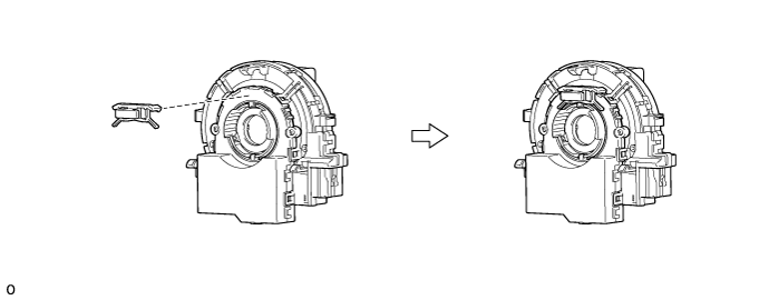
Note
-
Use the lock pin provided with a new spiral cable.
-
Do not remove the lock pin before the spiral cable is installed to the steering sensor.
-
-
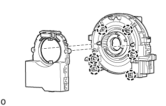
Detach the 6 claws and remove the spiral cable from the steering sensor.
-