AUTOMATIC TRANSMISSION UNIT REASSEMBLY

-
BEARING POSITION
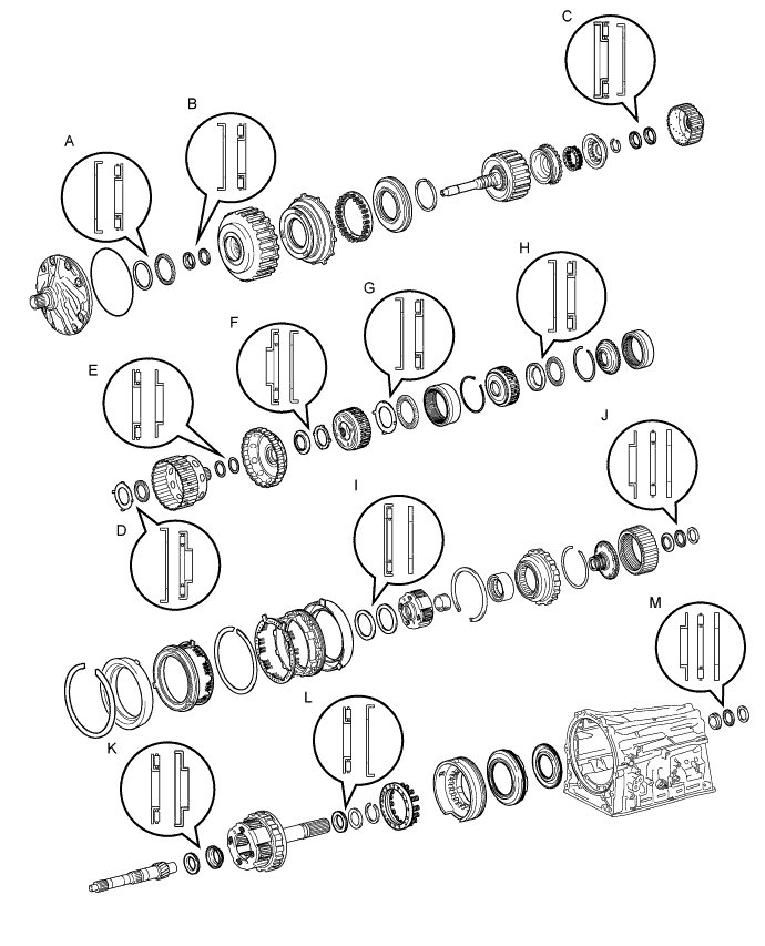
Mark Front Race Diameter
Inside / Outside (mm (in.))
Thrust Bearing Diameter
Inside / Outside (mm (in.))
Rear Race Diameter
Inside / Outside (mm (in.))
A 74.2 (2.921) / 87.74 (3.454) 71.9 (2.831) / 85.6 (3.370) - B 40.0 (1.575) / 52.8 (2.079) 34.6 (1.362) / 52.0 (2.047) - C 22.0 (0.890) / 44.8 (1.764) 21.3 (0.839) / 41.1 (1.618) - D 38.4 (1.512) / 56.5 (2.224) 33.3 (1.311) / 56.6 (2.228) - E - 40.83 (1.607) / 52.8 (2.079) 39.6 (1.559) / 52.8 (2.079) F - 37.1 (1.461) / 61.2 (2.409) 44.0 (1.732) / 62.8 (2.472) G 65.8 (2.591) / 86.3 (3.398) 63.3 (2.492) / 78.8 (3.102) - H 66.3 (2.610) / 78.9 (3.106) 63.3 (2.492) / 78.8 (3.102) - I - 55.7 (2.193) / 76.4 (3.008) 53.7 (2.114) / 74.0 (2.913) J 33.4 (1.315) / 49.0 (1.929) 32.1 (1.264) / 49.35 (1.943) 32.1 (1.264) / 49.0 (1.929) K - 21.0 (0.827) / 41.5 (1.634) 23.13 (0.911) / 41.5 (1.634) L - 43.55 (1.715) / 61.0 (2.402) 47.1 (1.854) / 67.1 (2.642) M 36.1 (1.421) / 52.5 (2.067) 37.0 (1.457) / 51.2 (2.016) 36.1 (1.421) / 51.0 (2.008) -
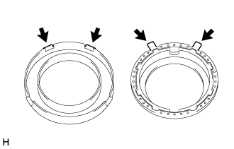
INSTALL BRAKE PLATE STOPPER SPRING
-
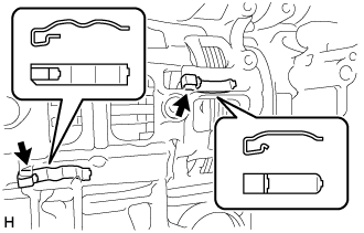
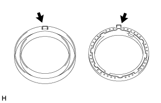
Install the 2 brake plate stopper springs to the automatic transmission case sub-assembly.
Note
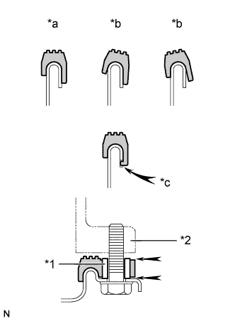
The shapes of the parts are different. Refer to the illustration when installing the parts.
-
-
INSTALL NO. 4 BRAKE PISTON
-
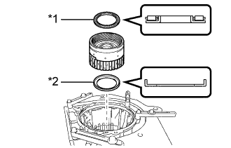
Coat 2 new O-rings with ATF, and install them to the brake reaction sleeve.
-
Coat 2 new O-rings with ATF, and install them to the No. 4 brake piston.
-
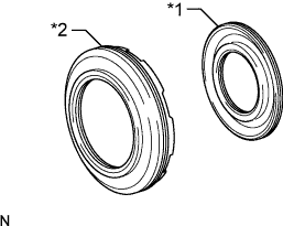
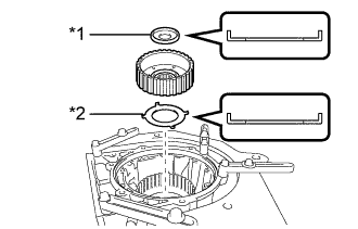
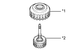
Text in Illustration *1 No. 4 Brake Piston *2 Brake Reaction Sleeve Install the No. 4 brake piston to the brake reaction sleeve.
Note
Be careful not to damage the O-rings.
-
-
INSTALL BRAKE REACTION SLEEVE
-
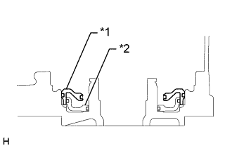
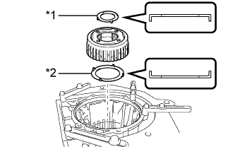
Text in Illustration *1 Brake Reaction Sleeve *2 No. 4 Brake Piston With the No. 4 brake piston underneath (the rear side), install the brake reaction sleeve and No. 4 brake piston to the automatic transmission case sub-assembly.
Note
Be careful not to damage the O-rings.
-
-
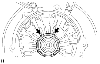
INSTALL 1ST AND REVERSE BRAKE PISTON
-
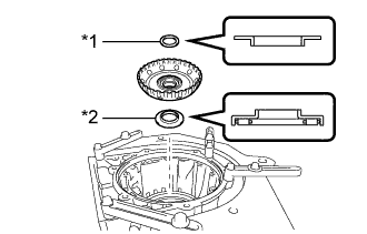
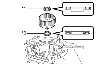
Coat a new O-ring with ATF, and install it to the 1st and reverse brake piston.
-
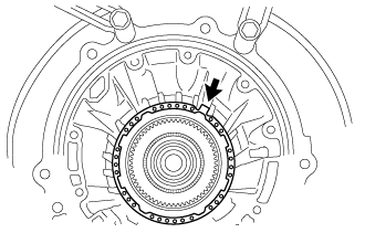
Install the 1st and reverse brake piston to the automatic transmission case sub-assembly while making sure that the protrusion of the 1st and reverse brake piston is positioned as shown in the illustration.
Note
Be careful not to damage the O-ring.
-
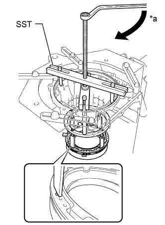
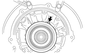
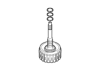
Install the 1st and reverse brake return spring sub-assembly to the automatic transmission case sub-assembly.
-
Place the 1st and reverse brake return spring sub-assembly onto the 1st and reverse brake piston.
-
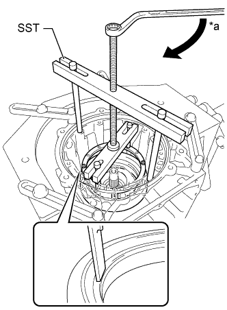
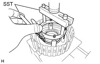
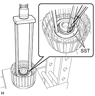
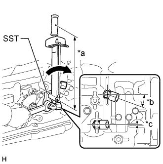
Text in Illustration *a Protective Tape Place SST on the 1st and reverse brake return spring sub-assembly, and compress the 1st and reverse brake return spring sub-assembly.
- SST
- 09380-60010 ( 09381-06030, 09381-06040, 09381-06080, 09381-06120, 09381-06130, 09381-05040, 09381-05050 )
-
Using a screwdriver, install the snap ring to the automatic transmission case sub-assembly.
Note
Be careful not to damage the 1st and reverse brake return spring sub-assembly and automatic transmission case sub-assembly.
Tech Tips
Tape the screwdriver tip before use.
-
-
INSTALL REAR PLANETARY GEAR ASSEMBLY
-
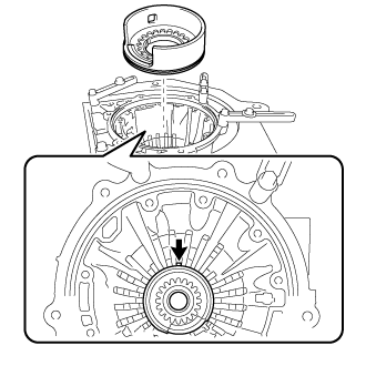
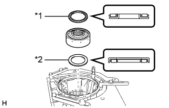
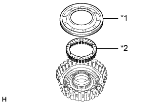
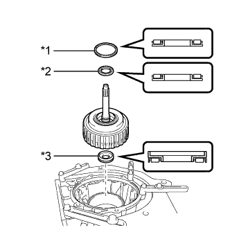
Text in Illustration *1 Thrust Needle Roller Bearing K *2 Thrust Bearing Race K *3 Thrust Needle Roller Bearing L *4 Thrust Bearing Race L Coat the thrust bearing race with ATF and install it to the automatic transmission case sub-assembly.
Thrust Needle Roller Bearing and Thrust Bearing Race Diameter Item Inside (mm (in.)) Outside (mm (in.)) Thrust Needle Roller Bearing K 21.0 (0.827) 41.5 (1.634) Thrust Bearing Race K 23.13 (0.911) 41.5 (1.634) Thrust Needle Roller Bearing L 43.55 (1.715) 61.0 (2.402) Thrust Bearing Race L 47.1 (1.854) 67.1 (2.642) Note
Be sure to install the thrust needle roller bearing and thrust bearing race in the correct direction.
-
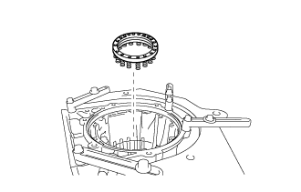
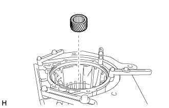
Coat the 2 thrust needle roller bearings and thrust bearing race with ATF and install them to the rear planetary gear assembly.
-
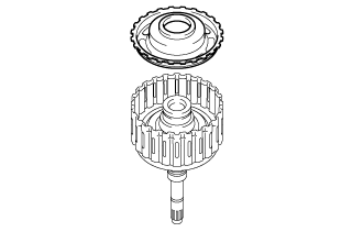
Install the rear planetary gear assembly to the automatic transmission case sub-assembly.
-
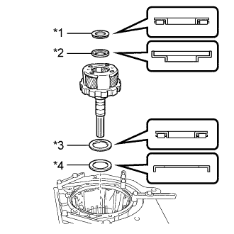
Text in Illustration *1 Thrust Bearing Race M
(Front Race)
*2 Thrust Needle Roller Bearing M *3 Thrust Bearing Race M
(Rear Race)
Coat the thrust needle roller bearing and 2 thrust bearing races with ATF and install it to the output shaft of the rear planetary gear assembly.
Bearing and Race Diameter Item Inside (mm (in.)) Outside (mm (in.)) Thrust Bearing Race M
(Front Race)
36.1 (1.421) 52.5 (2.067) Thrust Needle Roller Bearing M 37.0 (1.457) 51.2 (2.016) Thrust Bearing Race M
(Rear Race)
36.1 (1.421) 51.0 (2.008) Note
Be sure to install the thrust needle roller bearing and thrust bearing race in the correct direction.
-
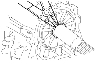
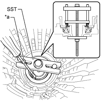
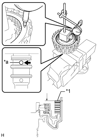
Using a snap ring expander, install the snap ring.
-
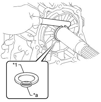
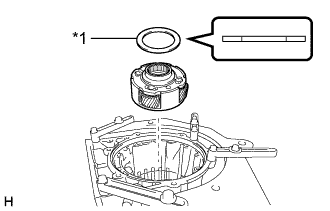
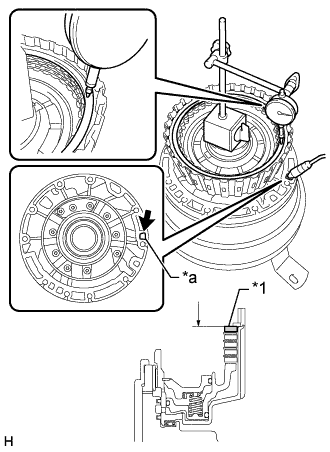
Text in Illustration *1 Thrust Bearing Race M
(Rear Race)
*a Mark Area Using a feeler gauge, measure the clearance between the snap ring and thrust bearing race.
Standard clearance 0.02 to 0.12 mm (0.000787 to 0.00472 in.) If the clearance is outside the standard range, select another thrust bearing race that brings the clearance within the standard range.
Tech Tips
There are 12 different thicknesses for the thrust bearing race.
Thrust Bearing Race Thickness Part No. Mark Thickness (mm (in.)) 35789-35060 
3.80 (0.150) 35789-50070 
3.85 (0.152) 35789-35070 
3.90 (0.154) 35789-50080 
3.95 (0.156) 35789-35080 
4.00 (0.157) 35789-50090 
4.05 (0.159) 35789-35090 
4.10 (0.161) 35789-50100 
4.15 (0.163) 35789-35100 
4.20 (0.165) 35789-50110 
4.25 (0.167) 35789-50120 
4.30 (0.169) 35789-50130 
4.35 (0.171)
-
-
INSTALL NO. 4 BRAKE DISC
-
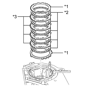
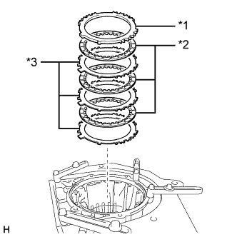
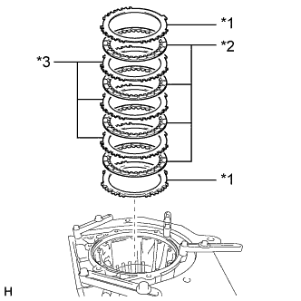
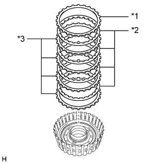
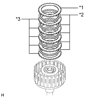
Text in Illustration *1 No. 4 Brake Flange *2 No. 4 Brake Disc *3 No. 4 Brake Plate Install the 2 No. 4 brake flanges, 5 No. 4 brake discs and 4 No. 4 brake plates to the automatic transmission case sub-assembly.
Note
-
Make sure that the No. 4 brake discs, No. 4 brake plates and No. 4 brake flanges are installed in the correct order.
-
Install the thicker No. 4 brake flange first, and then install the thinner one.
-
-
-
INSTALL INTERMEDIATE SHAFT
-
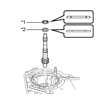
Text in Illustration *1 Thrust Needle Roller Bearing J *2 Thrust Bearing Race J Coat the thrust needle roller bearing and thrust bearing race with ATF and install them to the intermediate shaft.
Thrust Needle Roller Bearing and Thrust Bearing Race Diameter Item Inside (mm (in.)) Outside (mm (in.)) Thrust Needle Roller Bearing J 32.1 (1.264) 49.35 (1.943) Thrust Bearing Race J
(Rear Race)
32.1 (1.264) 49.0 (1.929) -
Install the intermediate shaft to the automatic transmission case sub-assembly.
-
-
INSTALL REAR PLANETARY RING GEAR
-
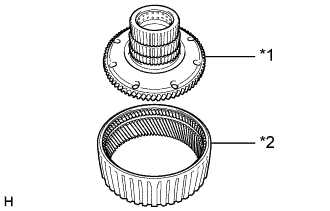
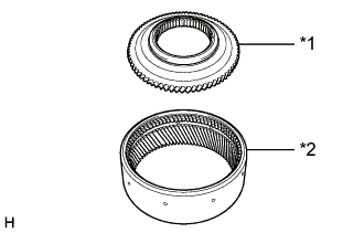
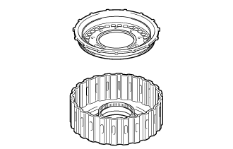
Text in Illustration *1 Rear Planetary Ring Gear Flange Sub-assembly *2 Rear Planetary Ring Gear Install the rear planetary ring gear to the rear planetary ring gear flange sub-assembly.
-
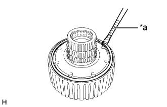
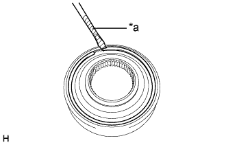
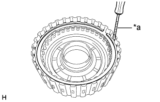
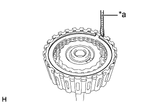
Text in Illustration *a Protective Tape Using a screwdriver, install the snap ring to the rear planetary ring gear flange sub-assembly with rear planetary ring gear.
Note
Be careful not to damage the rear planetary ring gear flange sub-assembly with rear planetary ring gear.
Tech Tips
Tape the screwdriver tip before use.
-
-
INSTALL REAR PLANETARY RING GEAR FLANGE SUB-ASSEMBLY WITH REAR PLANETARY RING GEAR
-
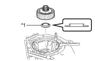
Text in Illustration *1 Thrust Bearing Race J Coat the thrust bearing race with ATF and install it to the rear planetary ring gear flange sub-assembly with rear planetary ring gear.
Thrust Bearing Race Diameter Item Inside (mm (in.)) Outside (mm (in.)) Thrust Bearing Race J
(Front Race)
33.4 (1.315.) 49.0 (1.929) Note
Be sure to install the thrust bearing race in the correct direction.
-
Install the rear planetary ring gear flange sub-assembly with rear planetary ring gear to the automatic transmission case sub-assembly.
-
-
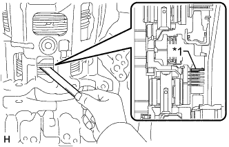
INSTALL ONE-WAY CLUTCH INNER RACE
-
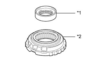
Text in Illustration *1 One-way Clutch Inner Race *2 No. 3 One-way Clutch Assembly Install the one-way clutch inner race to the No. 3 one-way clutch assembly.
Tech Tips
Rotate the one-way clutch inner race clockwise to install it.
-
-
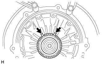
INSTALL NO. 3 ONE-WAY CLUTCH ASSEMBLY WITH ONE-WAY CLUTCH INNER RACE
-
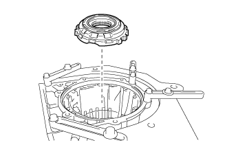
Install the No. 3 one-way clutch assembly with one-way clutch inner race to the automatic transmission case sub-assembly.
-
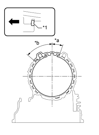
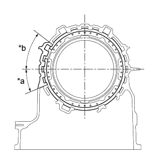
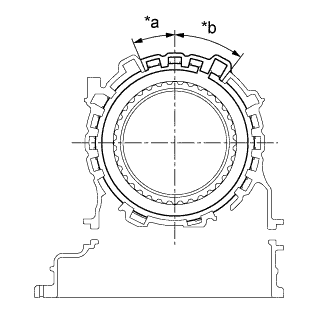
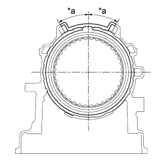
Text in Illustration *1 Snap Ring *a 19° *b 49° 
Front Side Using SST, install the snap ring to the automatic transmission case sub-assembly.
- SST
- 09350-30020 ( 09350-07060 )
Note
-
Install the snap ring so that the tapered side is facing out.
-
Be sure to install the snap ring so that the ends of the snap ring are within the area shown in the illustration.
-
-
INSPECT CLEARANCE OF NO. 4 BRAKE
-
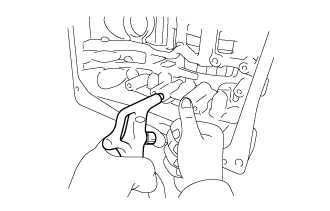
Make sure that the 1st and reverse brake piston moves smoothly when applying and releasing compressed air (392 kPa, 4.0 kgf/cm2, 57 psi).
-
Text in Illustration *1 Selected No. 4 Brake Flange Using a feeler gauge, measure the No. 4 brake pack clearance between the No. 4 brake disc and No. 4 brake flange.
Standard clearance 0.5 to 0.8 mm (0.0197 to 0.0314 in.) If the clearance is not as specified, select and install an appropriate No. 4 brake flange that will bring the clearance within the specified range.
No. 4 Brake Flange Thickness Mark Thickness (mm (in.)) 0 1.80 (0.0709) 1 1.97 (0.0776) 3 2.11 (0.0831) 4 2.25 (0.0886) 5 2.39 (0.0941) 7 2.53 (0.0996) 8 2.67 (0.105) 10 2.81 (0.111) 11 2.95 (0.116) 12 3.09 (0.122) 14 3.23 (0.127)
-
-
INSTALL NO. 1 BRAKE PISTON
-
Coat 2 new O-rings with ATF and install them to the No. 1 brake piston.
-
With the No. 1 brake piston return spring sub-assembly installed to the No. 1 brake piston, align the 2 claws of the No. 1 brake piston return spring sub-assembly with the 2 claws of the No. 1 brake cylinder, and then install the No. 1 brake piston to the No. 1 brake cylinder.
-
-
INSTALL NO. 1 BRAKE CYLINDER WITH NO. 1 BRAKE PISTON
-
Install the No. 1 brake cylinder with No. 1 brake piston to the automatic transmission case sub-assembly while making sure that the 2 claws of the No. 1 brake cylinder with No. 1 brake piston are positioned as shown in the illustration.
-
-
INSTALL NO. 1 BRAKE PISTON RETURN SPRING SUB-ASSEMBLY
-
Align the 2 claws of the No. 1 brake piston return spring sub-assembly with the 2 claws of the No. 1 brake cylinder, and then install the No. 1 brake piston return spring sub-assembly to the No. 1 brake piston.
-
Text in Illustration *a Turn Place SST on the No. 1 brake piston return spring sub-assembly, and compress the No. 1 brake piston return spring sub-assembly with a press.
- SST
- 09380-60010 ( 09381-06010, 09381-06040, 09381-06050, 09381-06070, 09381-06090, 09381-06100, 09381-06110, 09381-06120 )
-
Text in Illustration *a 22.5° *b 37.5° Using a screwdriver, install the snap ring to the automatic transmission case sub-assembly.
Note
-
Be sure to install the snap ring so that the ends of the snap ring are within the area shown in the illustration.
-
Be careful not to damage the automatic transmission case sub-assembly.
Tech Tips
Tape the screwdriver tip before use.
-
-
-
INSTALL NO. 1 BRAKE DISC
-
Text in Illustration *1 No. 1 Brake Flange *2 No. 1 Brake Disc *3 No. 1 Brake Plate Install the No. 1 brake flange, 3 No. 1 brake discs and 3 No. 1 brake plates to the automatic transmission case sub-assembly.
Note
Make sure that the No. 1 brake discs, No. 1 brake plates and No. 1 brake flange are installed in the correct order.
-
Text in Illustration *a 22.5° *b 37.5° Using a screwdriver, install the snap ring to the automatic transmission case sub-assembly.
Note
-
Be sure to install the snap ring so that the ends of the snap ring are within the area shown in the illustration.
-
Be careful not to damage the automatic transmission case sub-assembly.
Tech Tips
Tape the screwdriver tip before use.
-
-
-
INSPECT CLEARANCE OF NO. 1 BRAKE
-
Make sure that the No. 1 brake piston moves smoothly when applying and releasing compressed air (392 kPa, 4.0 kgf/cm2, 57 psi).
-
Text in Illustration *1 Selected No. 1 Brake Flange Using a feeler gauge, measure the No. 1 brake pack clearance between the No. 1 brake disc and No. 1 brake flange.
Standard clearance 0.3 to 0.6 mm (0.0119 to 0.0236 in.) If the clearance is not as specified, select and install an appropriate No. 1 brake flange that will bring the clearance within the specified range.
No. 1 Brake Flange Thickness Mark Thickness (mm (in.)) 0 4.9 (0.193) 1 5.0 (0.197) 2 5.1 (0.201) 3 5.2 (0.205) 4 5.3 (0.209) 5 5.4 (0.213) 6 5.5 (0.217) 7 5.6 (0.220) 8 5.7 (0.224) A 5.8 (0.228)
-
-
INSTALL PLANETARY SUN GEAR
-
Install the planetary sun gear to the automatic transmission case sub-assembly.
-
-
INSTALL CENTER PLANETARY GEAR ASSEMBLY
-
Text in Illustration *1 Thrust Bearing Race I Coat the thrust bearing race with ATF and install it to the center planetary gear assembly.
Thrust Bearing Race Diameter Item Inside (mm (in.)) Outside (mm (in.)) Thrust Bearing Race I 53.7 (2.114) 74.0 (2.913) -
Install the center planetary gear assembly to the automatic transmission case sub-assembly.
-
-
INSTALL CENTER PLANETARY RING GEAR
-
Text in Illustration *1 Center Planetary Ring Gear Flange *2 Center Planetary Ring Gear Install the center planetary ring gear to the center planetary ring gear flange
-
Text in Illustration *a Protective Tape Using a screwdriver, install the snap ring to the center planetary ring gear flange with center planetary ring gear.
Note
Be careful not to damage the center planetary ring gear flange with center planetary ring gear.
Tech Tips
Tape the screwdriver tip before use.
-
-
INSTALL CENTER PLANETARY RING GEAR FLANGE WITH CENTER PLANETARY RING GEAR
-
Text in Illustration *1 Thrust Needle Roller Bearing H *2 Thrust Needle Roller Bearing I Coat the 2 thrust needle roller bearings with ATF and install them to the center planetary ring gear flange with center planetary ring gear.
Thrust Needle Roller Bearing Diameter Item Inside (mm (in.)) Outside (mm (in.)) Thrust Needle Roller Bearing H 63.3 (2.492) 78.8 (3.102) Thrust Needle Roller Bearing I 55.7 (2.193) 76.4 (3.008) Note
Be sure to install the thrust needle roller bearing in the correct direction.
-
Install the center planetary ring gear flange with center planetary ring gear to the automatic transmission case sub-assembly.
-
-
INSTALL NO. 2 BRAKE DISC
-
Text in Illustration *1 No. 2 Brake Flange *2 No. 2 Brake Disc *3 No. 2 Brake Plate Install the 2 No. 2 brake flanges, 4 No. 2 brake discs and 3 No. 2 brake plates to the automatic transmission case sub-assembly.
Note
Make sure that the No. 2 brake discs, No. 2 brake plates and No. 2 brake flanges are installed in the correct order.
-
-
INSTALL NO. 2 BRAKE PISTON
-
Coat 2 new O-rings with ATF and install them to the No. 2 brake piston.
-
With the No. 2 brake piston return spring sub-assembly installed to the No. 2 brake piston, align the claw of the No. 2 brake piston return spring sub-assembly with the claw of the No. 2 brake cylinder, and then install the No. 2 brake piston to the No. 2 brake cylinder.
Note
Be careful not to damage the O-rings.
-
-
INSTALL NO. 2 BRAKE CYLINDER WITH NO. 2 BRAKE PISTON
-
Install the No. 2 brake piston return spring sub-assembly to the automatic transmission case sub-assembly while making sure that the claw of the No. 2 brake piston return spring sub-assembly is positioned as shown in the illustration.
-
Install the No. 2 brake cylinder with No. 2 brake piston to the automatic transmission case sub-assembly while making sure that the claw of the No. 1 brake cylinder with No. 1 brake piston is positioned as shown in the illustration.
-
Text in Illustration *a Turn Place SST on the No. 2 brake cylinder, and compress the No. 2 brake piston return spring sub-assembly with a press.
- SST
- 09380-60010 ( 09381-06010, 09381-06020, 09381-06040, 09381-06050, 09381-06060, 09381-06090, 09381-06100, 09381-06110, 09381-06120 )
-
Text in Illustration *a 30° Using a screwdriver, install the snap ring to the automatic transmission case sub-assembly.
Note
-
Be sure to install the snap ring so that the ends of the snap ring are within the area shown in the illustration.
-
Be careful not to damage the automatic transmission case sub-assembly.
Tech Tips
Tape the screwdriver tip before use.
-
-
-
INSPECT CLEARANCE OF NO. 2 BRAKE
-
Make sure that the No. 2 brake piston moves smoothly when applying and releasing compressed air (392 kPa, 4.0 kgf/cm2, 57 psi).
-
Text in Illustration *1 Selected No. 2 Brake Flange Using a feeler gauge, measure the No. 2 brake pack clearance between the No. 2 brake disc and No. 2 brake flange.
Standard clearance 0.4 to 0.7 mm (0.0158 to 0.0275 in.) If the clearance is not as specified, select and install an appropriate No. 2 brake flange that will bring the clearance within the specified range.
No. 2 Brake Flange Thickness Mark Thickness (mm (in.)) 0 2.0 (0.0787) 1 2.1 (0.0827) 2 2.2 (0.0866) 3 2.3 (0.0906) 4 2.4 (0.0945) 5 2.5 (0.0984) 6 2.6 (0.102) 7 2.7 (0.106) 8 2.8 (0.110)
-
-
INSTALL FRONT PLANETARY RING GEAR FLANGE SUB-ASSEMBLY
-
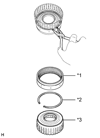
Text in Illustration *1 Front Planetary Ring Gear *2 Snap Ring *3 Front Planetary Ring Gear Flange Sub-assembly Set the snap ring onto the front planetary ring gear flange sub-assembly. Using needle-nose pliers, insert the snap ring into the front planetary ring gear while squeezing it, and then expand the snap ring to install it.
Note
Make sure the snap ring is securely inserted into the groove of the front planetary ring gear.
-
-
INSTALL FRONT PLANETARY RING GEAR WITH FRONT PLANETARY RING GEAR FLANGE SUB-ASSEMBLY
-
Text in Illustration *1 Thrust Needle Roller Bearing G *2 Thrust Bearing Race H Coat the thrust needle roller bearing and thrust bearing race with ATF and install them to the front planetary ring gear with front planetary ring gear flange sub-assembly.
Thrust Needle Roller Bearing and Thrust Bearing Race Diameter Item Inside (mm (in.)) Outside (mm (in.)) Thrust Needle Roller Bearing G 63.3 (2.492) 78.8 (3.102) Thrust Bearing Race H 66.3 (2.610) 78.9 (3.106) Note
Be sure to install the thrust needle roller bearing and thrust bearing race in the correct direction.
-
Install the front planetary ring gear with front planetary ring gear flange sub-assembly to the automatic transmission case sub-assembly.
-
-
INSTALL FRONT PLANETARY GEAR ASSEMBLY
-
Text in Illustration *1 Thrust Bearing Race F *2 Thrust Bearing Race G Coat the 2 thrust bearing races with ATF and install them to the front planetary gear assembly.
Thrust Bearing Race Diameter Item Inside (mm (in.)) Outside (mm (in.)) Thrust Bearing Race F 44.0 (1.732) 62.8 (2.472) Thrust Bearing Race G 65.8 (2.591) 86.3 (3.398) Note
Be sure to install the thrust bearing race in the correct direction.
-
Install the front planetary gear assembly to the automatic transmission case sub-assembly.
-
-
INSTALL SUN GEAR INPUT DRUM SUB-ASSEMBLY
-
Text in Illustration *1 Thrust Bearing Race E *2 Thrust Needle Roller Bearing F Coat the thrust needle roller bearing and thrust bearing race with ATF and install them to the sun gear input drum sub-assembly.
Thrust Needle Roller Bearing and Thrust Bearing Race Diameter Item Inside (mm (in.)) Outside (mm (in.)) Thrust Bearing Race E 40.83 (1.607) 52.8 (2.079) Thrust Needle Roller Bearing F 37.1 (1.461) 61.2 (2.409) Note
Be sure to install the thrust needle roller bearing and thrust bearing race in the correct direction.
-
Install the sun gear input drum sub-assembly to the automatic transmission case sub-assembly.
-
-
INSTALL FORWARD CLUTCH HUB SUB-ASSEMBLY
-
Text in Illustration *1 Thrust Needle Roller Bearing D *2 Thrust Needle Roller Bearing E Coat the 2 thrust needle roller bearings with ATF and install them to the forward clutch hub sub-assembly.
Thrust Needle Roller Bearing Diameter Item Inside (mm (in.)) Outside (mm (in.)) Thrust Needle Roller Bearing D 33.3 (1.311) 56.6 (2.228) Thrust Needle Roller Bearing E 39.6 (1.559) 52.8 (2.079) Note
Be sure to install the thrust needle roller bearing in the correct direction.
-
Install the forward clutch hub sub-assembly to the automatic transmission case sub-assembly.
-
-
INSTALL MULTIPLE DISC CLUTCH HUB
-
Text in Illustration *1 Thrust bearing race C *2 Thrust bearing race D Coat the 2 thrust bearing races with ATF and install them to the multiple disc clutch hub.
Thrust Bearing Race Diameter Item Inside (mm (in.)) Outside (mm (in.)) Thrust bearing race C 22.6 (0.890) 44.8 (1.764) Thrust bearing race D 38.4 (1.512) 56.5 (2.224) Note
Be sure to install the thrust bearing race in the correct direction.
-
Install the multiple disc clutch hub to the automatic transmission case sub-assembly.
-
-
INSTALL DIRECT CLUTCH PISTON
-
Coat 2 new O-rings with ATF, and install them to the direct clutch piston.
-
Install the direct clutch piston to the direct clutch drum sub-assembly.
Note
Be careful not to damage the O-rings.
-
-
INSTALL NO. 2 CLUTCH BALANCER
-
Text in Illustration *1 No. 2 Clutch Balancer *2 Direct Clutch Return Spring Sub-assembly Install the direct clutch return spring sub-assembly to the direct clutch piston.
-
Coat a new O-ring with ATF, and install it to the No. 2 clutch balancer.
-
Install the No. 2 clutch balancer to the direct clutch drum sub-assembly.
Note
Be careful not to damage the O-ring.
-
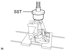
Place SST on the No. 2 clutch balancer, and compress the direct clutch return spring sub-assembly with a press.
- SST
- 09380-60010 ( 09381-06030, 09381-06040, 09381-06080, 09381-06100, 09381-06110 )
Note
Stop pressing when the spring sheet is lowered to the place 1 to 2 mm (0.0394 to 0.0787 in.) from the snap ring groove to prevent the spring sheet from being deformed.
-
Using SST, install the snap ring.
- SST
- 09350-30020 ( 09350-07070 )
Note
Do not expand the snap ring excessively.
-
-
INSTALL NO. 2 CLUTCH DISC (DIRECT CLUTCH DISC)
-
Text in Illustration *1 Direct Clutch Flange *2 No. 2 Clutch Disc *3 No. 2 Clutch Plate Install the 4 No. 2 clutch plates, 4 No. 2 clutch discs and direct clutch flange to the direct clutch drum sub-assembly.
Note
Make sure that the No. 2 clutch discs, No. 2 clutch plates and direct clutch flange are installed in the correct order.
-
Text in Illustration *a Protective Tape Using a screwdriver, install the snap ring to the direct clutch drum sub-assembly.
Note
Be careful not to damage the direct clutch drum sub-assembly.
Tech Tips
Tape the screwdriver tip before use.
-
-
INSPECT CLEARANCE OF NO. 2 CLUTCH (DIRECT CLUTCH)
-
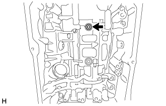
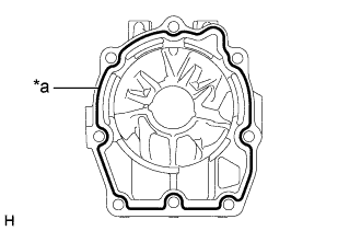
Text in Illustration *1 Selected Direct Clutch Flange *a Oil Hole Using a dial indicator, measure the clearance of the No. 2 clutch at several points while applying compressed air (196 kPa, 2.0 kgf/cm2, 28 psi) to the oil hole as shown in the illustration, and calculate the average.
Standard clearance 0.4 to 0.7 mm (0.0157 to 0.0275 in.) If the clearance is not as specified, select and install an appropriate direct clutch flange that will bring the clearance within the specified range.
Tech Tips
There are direct clutch flanges of different thicknesses.
Direct Clutch Flange Thickness Part No. Thickness (mm (in.)) 35675-71010 3.0 (0.118) 35675-71020 3.1 (0.122) 35675-71030 3.2 (0.126) 35675-71040 3.3 (0.130) 35675-71050 3.4 (0.134) 35675-71060 3.5 (0.138) 35675-71070 3.6 (0.142) 35675-71080 3.7 (0.146) 35675-71090 3.8 (0.150)
-
-
INSTALL FORWARD CLUTCH PISTON
-
Coat a new O-ring with ATF, and install it to the input shaft sub-assembly.
-
Coat a new O-ring with ATF, and install it to the forward clutch piston.
-
Install the forward clutch piston to the input shaft sub-assembly.
Note
Be careful not to damage the O-rings.
-
-
INSTALL NO. 1 CLUTCH BALANCER
-
Coat a new O-ring with ATF, and install it to the No. 1 clutch balancer.
-
Text in Illustration *1 No. 1 Clutch Balancer *2 Forward Clutch Return Spring Sub-assembly Install the forward clutch return spring sub-assembly and No. 1 clutch balancer to the input shaft sub-assembly.
Note
Be careful not to damage the O-ring.
-
Place SST on the No. 1 clutch balancer, and compress the forward clutch return spring sub-assembly with a press.
- SST
- 09387-00110
Note
Stop pressing when the spring sheet is lowered to the place 1 to 2 mm (0.0394 to 0.0787 in.) from the snap ring groove to prevent the spring sheet from being deformed.
-
Using SST, install the snap ring.
- SST
- 09350-30020 ( 09350-07070 )
Note
Do not expand the snap ring excessively.
-
-
INSTALL NO. 1 CLUTCH DISC (FORWARD CLUTCH DISC)
-
Text in Illustration *1 Forward Clutch Flange *2 No. 1 Clutch Disc *3 No. 1 Clutch Plate Install the 5 No. 1 clutch plates, 5 No. 1 clutch discs and forward clutch flange to the input shaft sub-assembly.
Note
Make sure that the No. 1 clutch discs, No. 1 clutch plates and forward clutch flange are installed in the correct order.
-
Text in Illustration *a Protective Tape Using a screwdriver, install the snap ring.
Note
Be careful not to damage the input shaft sub-assembly.
Tech Tips
Tape the screwdriver tip before use.
-
-
INSPECT CLEARANCE OF NO. 1 CLUTCH (FORWARD CLUTCH DISC)
-
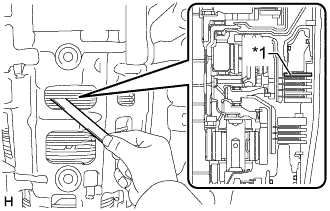
Text in Illustration *1 Selected Forward Clutch Flange *a Oil Hole Using a dial indicator, measure the clearance of the No. 1 clutch at several points while applying compressed air (196 kPa, 2.0 kgf/cm2, 28 psi) to the oil hole as shown in the illustration, and calculate the average.
Standard clearance 0.75 to 1.05 mm (0.0295 to 0.0413 in.) If the clearance is not as specified, select and install an appropriate forward clutch flange that will bring the clearance within the specified range.
Tech Tips
There are forward clutch flanges of different thicknesses.
Forward Clutch Flange Thickness Part No. Thickness (mm (in.)) 35635-71010 3.0 (0.118) 35635-71020 3.1 (0.122) 35635-71030 3.2 (0.126) 35635-71040 3.3 (0.130) 35635-71050 3.4 (0.134) 35635-71060 3.5 (0.138) 35635-71070 3.6 (0.142) 35635-71080 3.7 (0.146) 35635-71090 3.8 (0.150) 35635-71100 3.9 (0.154) 35635-71110 4.0 (0.157) 35635-71120 4.1 (0.161) 35635-71130 4.2 (0.165)
-
-
INSTALL CLUTCH DRUM OIL SEAL RING
-
Coat 3 new clutch drum oil seal rings with ATF and install them to the input shaft sub-assembly.
Note
Do not expand the clutch drum oil seal ring ends excessively.
Tech Tips
After installing the clutch drum oil seal rings, check that they rotate smoothly.
-
-
INSTALL DIRECT CLUTCH DRUM SUB-ASSEMBLY
-
Text in Illustration *1 Direct Clutch Drum Sub-assembly *2 Input Shaft Sub-assembly Install the direct clutch drum sub-assembly to the input shaft sub-assembly.
-
-
INSTALL CLUTCH DRUM AND INPUT SHAFT ASSEMBLY
-
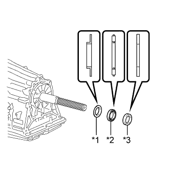
Text in Illustration *1 Thrust Needle Roller Bearing A *2 Thrust Needle Roller Bearing B *3 Thrust Needle Roller Bearing C Coat the 3 thrust needle roller bearings with ATF and install them to the clutch drum and input shaft assembly.
Thrust Needle Roller Bearing Diameter Item Inside (mm (in.)) Outside (mm (in.)) Thrust Needle Roller Bearing A 71.9 (2.831) 85.6 (3.370) Thrust Needle Roller Bearing B 34.6 (1.362) 52.0 (2.047) Thrust Needle Roller Bearing C 21.3 (0.839) 41.1 (1.618) Note
Be sure to install the thrust needle roller bearing in the correct direction.
-
Install the clutch drum and input shaft assembly to the automatic transmission case sub-assembly.
-
-
INSTALL OIL PUMP ASSEMBLY
-
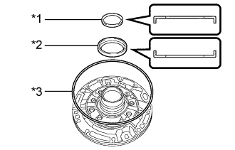
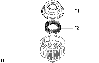
Text in Illustration *1 Thrust Bearing Race B *2 Thrust Bearing Race A *3 Oil Pump O-ring Coat the 2 thrust bearing races with ATF and install them to the oil pump assembly.
Race Diameter Item Inside (mm (in.)) Outside (mm (in.)) Thrust Bearing Race B 40.0 (1.575) 52.8 (2.079) Thrust Bearing Race A 74.2 (2.921) 87.74 (3.454) Note
Be sure to install the thrust bearing race in the correct direction.
-
Coat a new oil pump O-ring with ATF, and install it to the oil pump assembly.
-
Set the oil pump assembly on the input shaft, and align the bolt holes of the oil pump assembly with the automatic transmission case sub-assembly.
Note
Be careful not to damage the oil pump O-ring.
-
Temporarily install the oil pump assembly to the automatic transmission case sub-assembly.
-
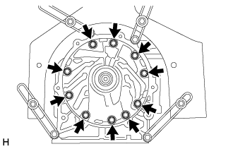
Install the oil pump assembly with the 10 bolts.
- Torque:
- 21 N*m { 215 kgf*cm, 16 ft.*lbf }
-
-
INSTALL MANUAL VALVE LEVER SHAFT OIL SEAL
-
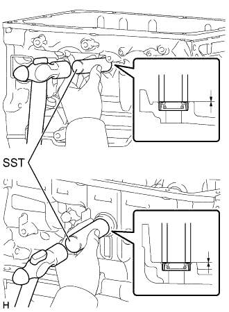
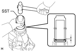
Using SST and a hammer, drive in 2 new manual valve lever shaft oil seals to the automatic transmission case sub-assembly.
- SST
- 09350-30020 ( 09350-07110 )
Standard depth -0.5 to 0.5 mm (-0.0196 to 0.0196 in.) -
Coat the lip of the manual valve lever shaft oil seal with MP grease.
-
-
INSTALL MANUAL VALVE LEVER SUB-ASSEMBLY
-
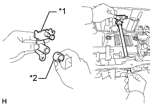
Text in Illustration *1 Manual Valve Lever Sub-assembly *2 Spacer Install a new spacer to the manual valve lever sub-assembly.
-
Install the manual valve lever shaft to the automatic transmission case sub-assembly through the manual valve lever sub-assembly.
-
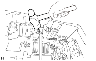
Using a hammer, drive in a new spring pin.
-
Turn the spacer and manual valve lever shaft to align the smaller hole on the spacer with the indent on the manual valve lever sub-assembly.
-
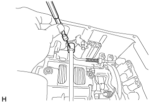
Using a 3 mm pin punch and a hammer, stake the spacer.
-
Check that the spacer does not turn.
-
Make sure that the shaft rotates smoothly.
-
-
INSTALL PARKING LOCK PAWL SHAFT
-
Install the E-ring to the parking lock pawl shaft.
-
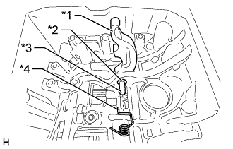
Text in Illustration *1 Parking Lock Pawl *2 E-ring *3 Parking Lock Pawl Shaft *4 Spring Install the parking lock pawl, parking lock pawl shaft and spring to the automatic transmission case sub-assembly.
-
-
INSTALL PARKING LOCK ROD SUB-ASSEMBLY
-
Install the parking lock rod sub-assembly to the manual valve lever sub-assembly.
-
-
INSTALL PARKING LOCK PAWL BRACKET
-
Install the parking lock pawl bracket to the automatic transmission case sub-assembly with the 3 bolts.
- Torque:
- 18 N*m { 184 kgf*cm, 13 ft.*lbf }
-
Move the manual valve lever sub-assembly to P, and check the output shaft is locked by the parking lock pawl.
-
-
INSTALL BRAKE DRUM GASKET
-
Install 2 new brake drum gaskets to the automatic transmission case sub-assembly.
-
-
INSTALL TRANSMISSION CASE GASKET
-
Install 2 new transmission case gaskets to the automatic transmission case sub-assembly.
-
-
INSTALL TRANSMISSION VALVE BODY ASSEMBLY
-
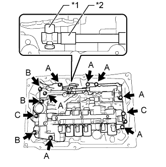
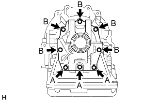
Text in Illustration *1 Manual Valve Lever Sub-assembly *2 Manual Valve Insert the manual valve lever sub-assembly into the groove on the end of the manual valve and install the transmission valve body assembly to the automatic transmission case sub-assembly with the 12 bolts.
- Torque:
- 11 N*m { 112 kgf*cm, 8 ft.*lbf }
Tech Tips
Each bolt length is indicated below.
Bolt length Bolt A 25 mm (0.984 in.) Bolt B 36 mm (1.42 in.) Bolt C 50 mm (1.97 in.) -
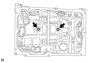
Install the detent spring and detent spring cover to the transmission valve body assembly with the bolt.
- Torque:
- 10 N*m { 102 kgf*cm, 7 ft.*lbf }
-
-
INSTALL VALVE BODY OIL STRAINER ASSEMBLY
-
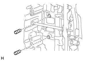
Coat a new O-ring with ATF, and install it to the valve body oil strainer assembly.
-
Install the valve body oil strainer assembly to the transmission valve body assembly with the 3 bolts.
- Torque:
- 10 N*m { 102 kgf*cm, 7 ft.*lbf }
-
-
INSTALL TRANSMISSION WIRE
-
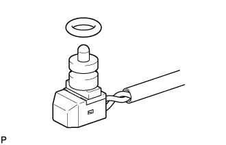
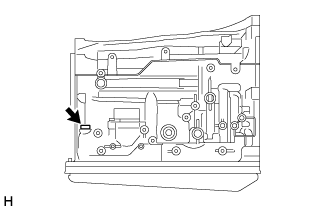
Coat 2 new O-rings with ATF, and install them to the 2 temperature sensors.
-
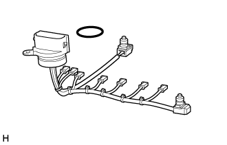
Coat a new O-ring with ATF, and install it to the transmission wire.
-
Install the transmission wire to the automatic transmission case sub-assembly with the bolt.
- Torque:
- 5.4 N*m { 55 kgf*cm, 48 in.*lbf }
-
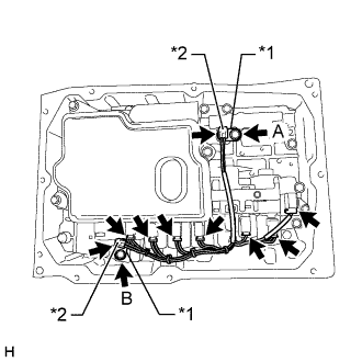
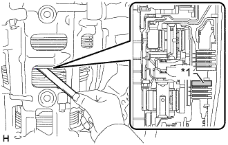
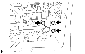
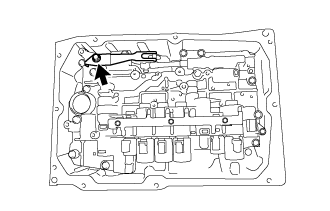
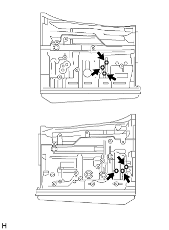
Text in Illustration *1 Temperature Sensor Clamp *2 Temperature Sensor Connect the 7 solenoid valve connectors.
-
Install the 2 temperature sensors and 2 temperature sensor clamps to the transmission valve body assembly with the bolt.
- Torque:
- for Bolt A
- 10 N*m { 102 kgf*cm, 7 ft.*lbf }
- for Bolt B
- 11 N*m { 112 kgf*cm, 8 ft.*lbf }
-
-
INSTALL AUTOMATIC TRANSMISSION OIL PAN SUB-ASSEMBLY
-
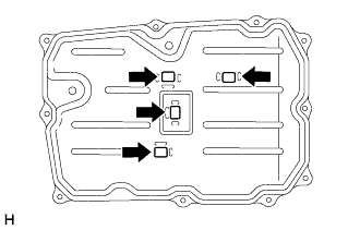
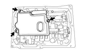
Install the 4 transmission oil cleaner magnets to the automatic transmission oil pan sub-assembly as shown in the illustration.
-
Install a new automatic transmission oil pan gasket to the automatic transmission oil pan sub-assembly.
-
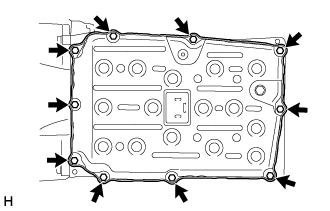
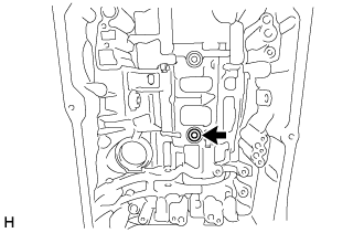
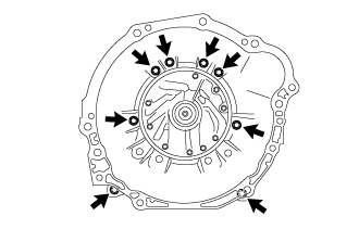
Install the automatic transmission oil pan sub-assembly with automatic transmission oil pan gasket to the automatic transmission case sub-assembly with the 10 bolts.
- Torque:
- 7.4 N*m { 75 kgf*cm, 65 in.*lbf }
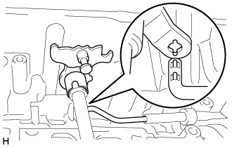
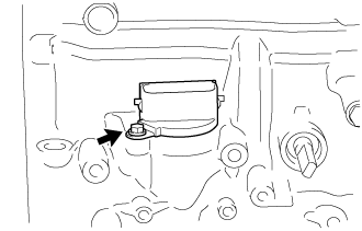
Text in Illustration *1 Sleeve *2 Automatic Transmission Case Sub-assembly *a Correct *b Incorrect *c Protrusion Note
-
Make sure that automatic transmission oil pan gasket seal surface and automatic transmission oil pan sub-assembly contact surface are free of oil and foreign matter.
-
Install the automatic transmission oil pan gasket so that there is no slack in the automatic transmission oil pan gasket, and the entire seal surface is level.
-
Make sure that the 8 protrusions are properly engaged to the automatic transmission oil pan sub-assembly.
-
When installing the automatic transmission oil pan sub-assembly, make sure that the automatic transmission oil pan gasket is not pinched between the sleeve and the seal surface of the automatic transmission case sub-assembly.
-
Install the drain plug and a new gasket to the automatic transmission oil pan sub-assembly.
- Torque:
- 20 N*m { 204 kgf*cm, 15 ft.*lbf }
-
Using a 5 mm hexagon socket wrench, install a new gasket and overflow plug to the automatic transmission oil pan sub-assembly.
- Torque:
- 20 N*m { 204 kgf*cm, 15 ft.*lbf }
-
-
INSTALL AUTOMATIC TRANSMISSION HOUSING
-
Clean and degrease the bolts and bolt holes with non-residue solvent.
-
Install the automatic transmission housing to the automatic transmission case sub-assembly with the 8 bolts.
- Torque:
- 34 N*m { 345 kgf*cm, 25 ft.*lbf }
-
Apply adhesive to 2 or 3 threads on the end of the 4 bolts.
Adhesive Toyota Genuine Adhesive 1344, Three Bond 1344 or equivalent -
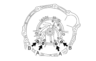
Install 4 bolts to the automatic transmission housing.
- Torque:
- for Bolt A (M10 bolt)
- 34 N*m { 345 kgf*cm, 25 ft.*lbf }
- for Bolt B (M12 bolt)
- 57 N*m { 579 kgf*cm, 42 ft.*lbf }
-
-
INSTALL AUTOMATIC TRANSMISSION EXTENSION HOUSING OIL SEAL
-
Using SST and a hammer, drive in the automatic transmission extension housing oil seal to the extension housing sub-assembly.
- SST
- 09309-37010
Standard depth 5.4 to 5.8 mm (0.213 to 0.228 in.) -
Coat the lip of a new automatic transmission extension housing oil seal with MP grease.
-
-
INSTALL EXTENSION HOUSING DUST DEFLECTOR
-
Using SST and a press, install a new extension housing dust deflector to the extension housing sub-assembly.
- SST
- 09950-60020 ( 09951-01030 )
-
-
INSTALL EXTENSION HOUSING SUB-ASSEMBLY
-
Clean and degrease the threads of the 8 bolts, bolt holes and the contact surfaces of the automatic transmission case sub-assembly and extension housing sub-assembly with non-residue solvent.
-
Text in Illustration *a Seal Packing Apply seal packing to the extension housing sub-assembly as shown in the illustration.
Seal packing Toyota Genuine Seal Packing 1281, Three Bond 1281 or equivalent Note
-
Apply seal packing in a continuous line (width 1.2 mm (0.0472 in.)) along the sealing surface.
-
After applying seal packing, install the extension housing sub-assembly to the automatic transmission case sub-assembly within 3 minutes and tighten the bolts within 10 minutes.
-
-
Apply adhesive to 2 or 3 threads on the end of the 8 bolts.
Adhesive Toyota Genuine Adhesive 1344, Three Bond 1344 or equivalent -
Install the extension housing sub-assembly to the automatic transmission case sub-assembly with the 8 bolts.
- Torque:
- 34 N*m { 345 kgf*cm, 25 ft.*lbf }
Tech Tips
Each bolt length is indicated below.
Bolt length for Bolt A 40 mm (1.57 in.) for Bolt B 45 mm (1.77 in.)
-
-
INSTALL OIL COOLER TUBE UNION
-
Coat 2 new O-rings with ATF and install them to the 2 oil cooler tube unions.
-
Text in Illustration *a Torque Wrench Fulcrum Length *b 18° to 22° *c -2° to 2° Using SST, install the 2 oil cooler tube unions to the automatic transmission case sub-assembly.
- SST
- 09268-78010
- Torque:
- 29 N*m { 300 kgf*cm, 22 ft.*lbf }
Tech Tips
-
Calculate the torque wrench reading when changing the fulcrum length of the torque wrench.
-
When using SST (fulcrum length of 34.5 mm (1.3583 in.)) + torque wrench (fulcrum length of 180 mm (7.0866 in.)): 25 N*m (252 kgf*cm, 18 ft.*lbf)
-
-
INSTALL AUTOMATIC TRANSMISSION CASE PLUG
-
Coat 6 new O-rings with ATF, and install them to the 6 automatic transmission case plugs.
-
Install the 6 automatic transmission case plugs to the automatic transmission case sub-assembly.
- Torque:
- 7.4 N*m { 75 kgf*cm, 65 in.*lbf }
-
Coat a new O-ring with ATF, and install it to the automatic transmission case plug.
-
Using a T55 "TORX" socket wrench, install the automatic transmission case plug to the automatic transmission case sub-assembly.
- Torque:
- 39 N*m { 400 kgf*cm, 29 ft.*lbf }
-
-
INSTALL REFILL PLUG
-
Coat a new O-ring with ATF, and install it to the refill plug.
-
Install the refill plug to the extension housing sub-assembly.
- Torque:
- 39 N*m { 400 kgf*cm, 29 ft.*lbf }
-
-
INSTALL PARK/NEUTRAL POSITION SWITCH ASSEMBLY
Tech Tips
Make sure that the manual valve lever shaft has not been rotated prior to installing the park/neutral position switch assembly as the detent spring may become detached from the manual valve lever shaft.
-
Clean the bolt and bolt hole.
-
Apply adhesive to 2 or 3 threads on the end of the bolt.
Adhesive Toyota Genuine Adhesive 1344, Three Bond 1344 or equivalent Note
Install the bolt within 3 minutes of applying adhesive.
-
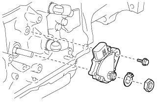
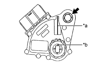
Temporarily install the park/neutral position switch assembly to the automatic transmission case sub-assembly with the bolt.
-
Install a lock washer and nut to the park/neutral position switch assembly.
- Torque:
- 6.9 N*m { 70 kgf*cm, 61 in.*lbf }
-
Temporarily install the transmission control shaft lever LH to the manual valve lever shaft with the spring washer and nut.
-
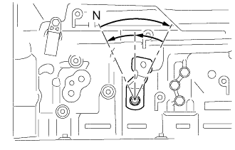
Turn the transmission control shaft lever clockwise until it stops, and then return the transmission control shaft lever counterclockwise 2 notches to N.
-
Text in Illustration *a Neutral Basic Line *b Groove Align the neutral basic line with the groove as shown in the illustration, and tighten the bolt.
- Torque:
- 13 N*m { 130 kgf*cm, 9 ft.*lbf }
-
Using a screwdriver, bend the tabs of the lock washer.
Note
-
Be careful not to damage the park/neutral position switch assembly.
-
Bend at least 2 of the lock washer tabs.
Tech Tips
Tape the screwdriver tip before use.
-
-
-
INSTALL TRANSMISSION CONTROL SHAFT LEVER LH
-
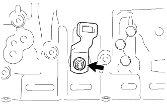
Install the transmission control shaft lever LH to the manual valve lever shaft with the spring washer and nut.
- Torque:
- 16 N*m { 160 kgf*cm, 12 ft.*lbf }
-
-
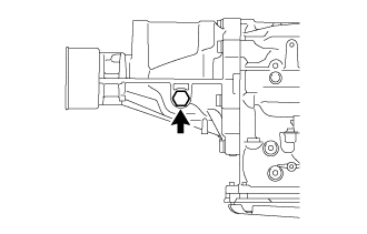
INSTALL TRANSMISSION REVOLUTION SENSOR
-
Coat a new O-ring with ATF, and install it to the transmission revolution sensor NT.
-
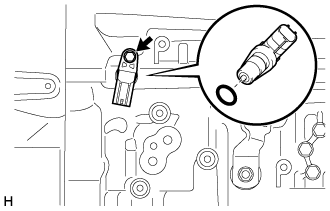
Install the transmission revolution sensor NT to the automatic transmission case sub-assembly with the bolt.
- Torque:
- 5.4 N*m { 55 kgf*cm, 48 in.*lbf }
-
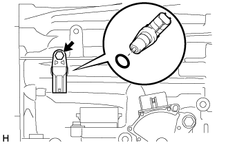
Coat a new O-ring with ATF, and install it to the transmission revolution sensor SP2.
-
Install the transmission revolution sensor SP2 to the automatic transmission case sub-assembly with the bolt.
- Torque:
- 5.4 N*m { 55 kgf*cm, 48 in.*lbf }
-
-
INSTALL BREATHER PLUG HOSE
-
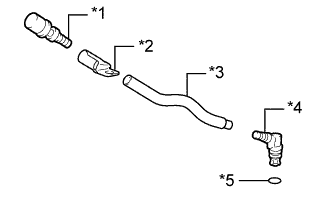
Text in Illustration *1 Breather Plug Sub-assembly *2 Clamp *3 Breather Plug Hose *4 Breather Plug *5 O-ring Install the breather plug sub-assembly, clamp and breather plug to the breather plug hose.
-
Coat a new O-ring with ATF, and install it to the breather plug.
-
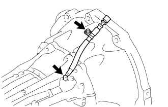
Install the breather plug hose to the automatic transmission case sub-assembly with the bolt.
- Torque:
- 5.4 N*m { 55 kgf*cm, 48 in.*lbf }
Note
Be careful not to damage the O-rings.
-