CYLINDER HEAD INSTALLATION

-
INSPECT CYLINDER HEAD SET BOLT
-
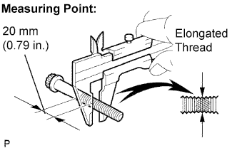
Using vernier calipers, measure the minimum diameter of the elongated thread at the measuring point.
Standard outside diameter 10.76 to 10.97 mm (0.4236 to 0.4319 in.) Minimum outside diameter 10.40 mm (0.4094 in.) Tech Tips
If there are no excessively thin areas found in the visual check, check the center of the bolt (see illustration) and find the area that has the lowest diameter.
-
-
INSTALL CYLINDER HEAD GASKET
-
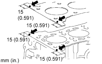
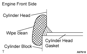
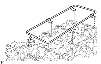
Apply a continuous bead of seal packing to the cylinder block upper side and cylinder head gasket upper side as shown in the illustration.
Seal packing Toyota Genuine Seal Packing 1282B, Three Bond 1282B or equivalent Seal width 4.0 to 7.0 mm (0.15 to 0.28 in.) Note
-
Remove any oil from the contact surface.
-
Install the cylinder head gasket within 3 minutes after applying the seal packing.
-
Install the cylinder head bolt within 15 minutes after applying the seal packing.
-
Do not put into engine oil within 4 hours of installation.
-
-
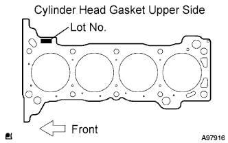
Place a new cylinder head gasket on the cylinder block surface with the Lot No. stamp upper side facing upward.
Note
-
Pay attention to the installation direction.
-
Place the cylinder head gently to prevent damage to the gasket with the bottom part of the head.
-
-
-
INSTALL CYLINDER HEAD SUB-ASSEMBLY
Tech Tips
The cylinder head bolts are tightened in 2 progressive steps.
-
Place the cylinder head on the cylinder block.
Note
Remove any dust and oil from the contact surface.
-
Apply a light coat of engine oil to the threads and under the heads of the cylinder head bolts.
-
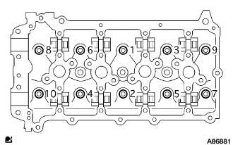
Install and uniformly tighten the 10 cylinder head bolts with the plate washers, in several steps, in the sequence shown.(*1)
- Torque:
- 39 N*m { 398 kgf*cm, 29 ft.*lbf }
-
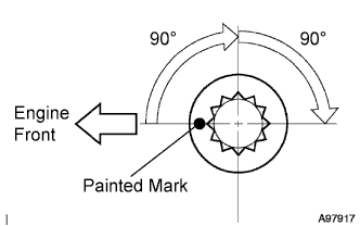
Mark the front of the cylinder head bolt head with paint.
-
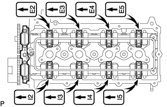
Retighten the cylinder head bolts by 90° in the order shown in step (*1).
-
Retighten the cylinder head bolts by an additional 90°.
-
Check that the painted mark is now facing rearward.
-
Seal packing will seep out on the engine's front side. Thoroughly wipe clean any seal packing.
-
-
INSTALL VALVE STEM CAP
-
Apply clean engine oil to the valve stem tip, and install the valve stem cap.
Note
Install the cap to the same place it was removed from.
-
-
INSTALL VALVE LASH ADJUSTER ASSEMBLY
Note
-
Install the cap to the same place it was removed from.
-
Use only clean engine oil.
-
After bleeding the air, when accidentally tipped over the lash adjuster because break put oil leaks from it, do air breed again.
-
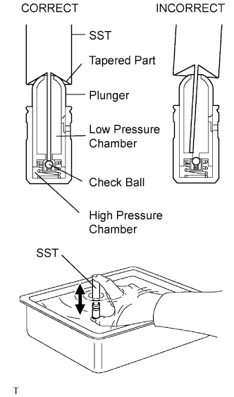
Place the lash adjuster into a container full of engine oil.
-
Insert the tip of SST into the lash adjuster's plunger and use the tip to press down on the checkball inside the plunger.
- SST
- 09276-75010
-
Squeeze the SST and lash adjuster together to move the plunger up and down 5 to 6 times.
-
Check the movement of the plunger and bleed air.
OK Plunger moves up and down. Note
When bleeding high-pressure air from the compression chamber, make sure that the tip of the SST is actually pressing the checkball as shown in the illustration. If the checkball is not pressed, air will not bleed.
-
After bleeding air, remove the SST. Then quickly and firmly press the plunger with a finger.
OK Plunger is very difficult to move. If the result is not as specified, replace the lash adjuster.
-
Install the lash adjuster.
Note
Install the lash adjuster to the same place it was removed from.
-
-
INSTALL VALVE ROCKER ARM SUB-ASSEMBLY NO.1
-
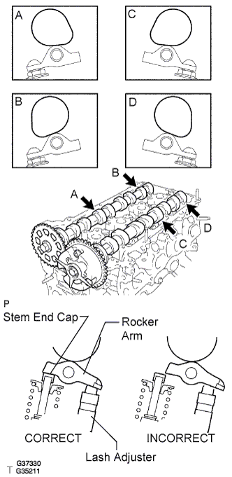
Apply clean engine oil to the valve lash adjuster tip and valve stem cap surface. Then install the valve rocker arm.
Note
Install the valve stem cap and valve rocker arm to the same places they were removed from.
-
-
INSTALL CAMSHAFTS
-
Apply clean engine oil to the camshaft's cam portion and the cylinder head journals.
-
Set the camshaft and No.2 camshaft as shown in the illustration.
Note
Before and after setting the camshaft and No.2 camshaft, firmly set the rocker arm to the lash adjuster.
-
-
INSTALL CAMSHAFT BEARING CAP
-
Temporarily install the camshaft bearing cap No.1.
-
Check the proper location of each camshaft bearing cap No.2 and install them.
-
Install a new O-ring to the camshaft bearing cap No.1.
-
Temporarily install the oil delivery pipe.
-
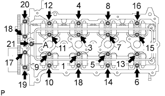
Tighten the 21 bolts and 20 washers in the order shown in the illustration.
- Torque:
- Bolt A
- 12 N*m { 122 kgf*cm, 9 ft.*lbf }
- Except bolt A
- 16 N*m { 160 kgf*cm, 11 ft.*lbf }
-
-
INSTALL CHAIN SUB-ASSEMBLY
-
INSTALL MANUAL TRANSMISSION UNIT ASSEMBLY (for Manual Transmission)
-
INSTALL AUTOMATIC TRANSMISSION ASSEMBLY (for Automatic Transmission)
-
CHECK FOR IDLE SPEED AND IGNITION TIMING
-
CHECK FOR CO/HC
-
CHECK FUNCTION OF THROTTLE BODY
-
Check the throttle control motor operating sounds.
-
Turn the ignition switch to the ON position.
-

When pressing the accelerator pedal, listen to the running sounds of the motor. Make sure no friction noise comes from the motor.
If friction noise exists, replace the throttle body.
-
-
Check the throttle position sensor.
-
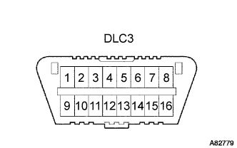
Connect the intelligent tester to the DLC3.
-
Turn the ignition switch to the ON position.
-
Turn the intelligent tester main switch on.
-
Enter the following menus: Power train / Engine / Data List / Throttle Sensor Position and Throttle Position Sensor Position #2.
-
Depress the accelerator pedal. When the throttle valve is fully opened, check that the value of the "Throttle Sensor Position" is within the specification.
Standard throttle valve opening percentage 60% or more Note
When checking the standard throttle valve opening percentage, the shift lever should be in the N position.
Tech Tips
If the percentage is less than 60%, replace the throttle body.
-
-
-
PERFORM INITIALIZATION