SFI SYSTEM (w/ Dual VVT-i), Diagnostic DTC:P0516, P0517
| DTC Code | DTC Name |
|---|---|
| P0516 | Battery Temperature Sensor Circuit Low |
| P0517 | Battery Temperature Sensor Circuit High |
DESCRIPTION
The battery temperature sensor (built into battery current sensor) detects battery temperature.
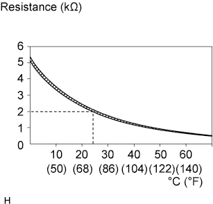
A thermistor is integrated into the battery temperature sensor, and the resistance in the battery temperature sensor changes according to the battery temperature.
The resistance of the thermistor in the battery temperature sensor decreases as the battery temperature increases. The resistance increases as the temperature decreases.
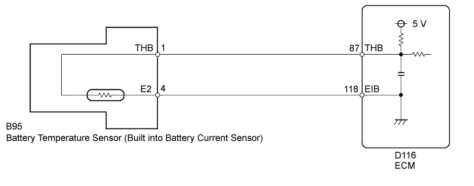
The battery temperature sensor is connected to the ECM. The ECM supplies 5 V from the THB terminal to the battery temperature sensor through resistor R.
The battery thermometer sensor and resistor R are connected in series. This results in fluctuations in the voltage supplied from the THB terminal when the resistance changes according to the battery temperature.
The ECM determines the battery temperature according to fluctuations in voltage. When the battery temperature is high, the ECM determines to reduce the amount of current supplied from the generator in order to protect the battery.
| DTC No. | DTC Detection Condition | Trouble Area |
|---|---|---|
| P0516 | Battery temperature sensor output value is less than 0.2 V for 0.5 seconds or more (1 trip detection logic) |
|
| P0517 | Battery temperature sensor output value is higher than 4.8 V for 0.5 seconds or more (1 trip detection logic) |
|
MONITOR STRATEGY
| Frequency of Operation | Continuous |
CONFIRMATION DRIVING PATTERN
-
Connect the GTS to the DLC3.
-
Turn the ignition switch to ON and turn the GTS on.
-
Clear the DTCs (even if no DTCs are stored, perform the clear DTC procedure).
-
Turn the ignition switch off and wait for at least 30 seconds.
-
Turn the ignition switch to ON and turn the GTS on.
-
Wait 5 seconds or more.
-
Enter the following menus: Powertrain / Engine and ECT / Trouble Codes.
-
Read the pending DTCs.
Tech Tips
-
If a pending DTC is output, the system is malfunctioning.
-
If a pending DTC is not output, perform the following procedure.
-
-
Enter the following menus: Powertrain / Engine and ECT / Utility / All Readiness.
-
Input the DTC: P0516, P0517.
-
Check the DTC judgment result.
GTS Display Description NORMAL
-
DTC judgment completed
-
System normal
ABNORMAL
-
DTC judgment completed
-
System abnormal
INCOMPLETE
-
DTC judgment completed
-
Perform driving pattern after confirming DTC enabling conditions
N/A
-
Unable to perform DTC judgment
-
Number of DTCs which do not fulfill DTC preconditions has reached ECU memory limit
Tech Tips
-
If the judgment result shows NORMAL, the system is normal.
-
If the judgment result shows ABNORMAL, the system has a malfunction.
-
If the judgment result shows INCOMPLETE or N/A, perform the Confirmation Driving Pattern and check the DTC judgment result again.
-
WIRING DIAGRAM
INSPECTION PROCEDURE
Tech Tips
Read freeze frame data using the GTS. Freeze frame data records the engine condition when malfunctions are detected. When troubleshooting, freeze frame data can help determine if the vehicle was moving or stationary, if the engine was warmed up or not, if the air fuel ratio was lean or rich, and other data from the time the malfunction occurred.
PROCEDURE
-
INSPECT BATTERY TEMPERATURE SENSOR
-
Inspect the battery temperature sensor Click here.
NG 
REPLACE BATTERY TEMPERATURE SENSOR
OK 
-
-
CHECK HARNESS AND CONNECTOR (BATTERY TEMPERATURE SENSOR - ECM)
-
Disconnect the battery temperature sensor connector.
-
Disconnect the ECM connector.
-
Measure the resistance according to the value(s) in the table below.
Standard Resistance Tester Connection Condition Specified Condition B95-1 (THB) - D116-87 (THB) Always Below 1 Ω B95-4 (E2) - D116-118 (EIB) Always Below 1 Ω B95-1 (THB) or D116-87 (THB) - Body ground Always 10 kΩ or higher
NG
REPAIR OR REPLACE HARNESS OR CONNECTOR
OK 
REPLACE ECM Click here
-