SFI SYSTEM (w/o Secondary Air Injection System) ECM Back-up Power Source Circuit
DESCRIPTION
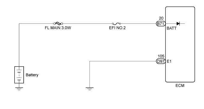
While the ignition switch is off, battery voltage is supplied to terminal BATT of the ECM for the DTC memory, air-fuel ratio adaptive control value memory, etc.
WIRING DIAGRAM
INSPECTION PROCEDURE
Note
-
After turning the ignition switch off, waiting time may be required before disconnecting the cable from the negative (-) battery terminal. Therefore, make sure to read the disconnecting the cable from the negative (-) battery terminal notices before proceeding with work Click here.
-
Inspect the fuses for circuits related to this system before performing the following inspection procedure.
PROCEDURE
-
CHECK HARNESS AND CONNECTOR (ECM - BATTERY)
-
Disconnect the ECM connector.
-
Disconnect the cable from the negative (-) battery terminal.
-
Disconnect the cable from the positive (+) battery terminal.
-
Measure the resistance according to the value(s) in the table below.
Standard Resistance Tester Connection Condition Specified Condition B71-20 (BATT) - Positive (+) battery cable terminal Always Below 1 Ω B71-20 (BATT) or positive (+) battery cable terminal - Body ground Always 10 kΩ or higher
NG 
REPAIR OR REPLACE HARNESS OR CONNECTOR
OK 
-
-
INSPECT BATTERY
-
Check that the battery is not depleted Click here.
OK Battery is not depleted.
NG
REPLACE BATTERY
OK
-
-
CHECK BATTERY TERMINAL
-
Check that the battery terminals are not loose or corroded.
OK Battery terminals are not loose or corroded.
NG
REPAIR BATTERY TERMINAL
OK
-
-
CHECK ECM (BATT VOLTAGE)
-
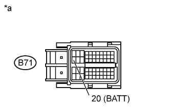
Text in Illustration *a Front view of wire harness connector
(to ECM)
Disconnect the ECM connector.
-
Measure the voltage according to the value(s) in the table below.
Standard Voltage Tester Connection Condition Specified Condition B71-20 (BATT) - Body ground Always 11 to 14 V
NG
PERFORM SIMULATION TEST Click here
OK 
REPLACE ECM Click here
-