SFI SYSTEM (w/ Secondary Air Injection System), Diagnostic DTC:P0340, P0341
| DTC Code | DTC Name |
|---|---|
| P0340 | Camshaft Position Sensor Circuit |
| P0341 | Camshaft Position Sensor "A" Circuit Range / Performance (Bank 1 or Single Sensor) |
DESCRIPTION
The camshaft position sensor consists of a magnet and an iron core which is wrapped with copper wire, and is installed on the cylinder head. When the camshaft rotates, each of the 3 teeth on the camshaft pass through the camshaft position sensor. This activates the internal magnet in the sensor, generating a voltage in the copper wire. The camshaft rotation is synchronized with the crankshaft rotation. When the crankshaft turns twice, the voltage is generated 3 times in the camshaft position sensor. The generated voltage in the sensor acts as a signal, allowing the ECM to locate the camshaft position. This signal is then used to control ignition timing, fuel injection timing, and the VVT system.
| DTC No. | DTC Detection Condition | Trouble Area |
|---|---|---|
| P0340 | When one of the following conditions is met:
|
|
| P0341 | When crankshaft rotates twice, The camshaft position sensor signal input to the ECM 12 times or more (1 trip detection logic). |
|
-
Tech Tips
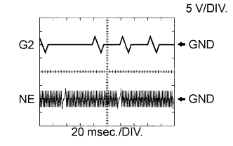
Reference: Inspection using an oscilloscope.
-
-
G2 stands for the camshaft position sensor signal and NE stands for the crankshaft position sensor signal.
-
Grounding failure of the shielded wire may cause noise in the waveforms.
Tester Connection Tool Setting Condition Specified Condition D97-93 (NE+) - D97-117 (NE-) 5 V/DIV, 20 msec./DIV. Idling The correct waveform is as shown D97-94 (G2) - D97-118 (G2-) 5 V/DIV, 20 msec./DIV. Idling The correct waveform is as shown -
MONITOR DESCRIPTION
If no signal is transmitted by the camshaft position sensor despite the engine running, or the rotations of the camshaft and crankshaft are not synchronized, the ECM interprets this as a malfunction of the circuit.
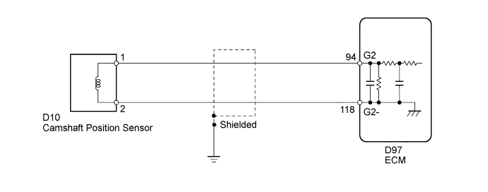
WIRING DIAGRAM
INSPECTION PROCEDURE
Tech Tips
Read freeze frame data using the intelligent tester. Freeze frame data records the engine conditions when malfunctions are detected. When troubleshooting, freeze frame data can help determine if the vehicle was moving or stationary, if the engine was warmed up or not, if the air-fuel ratio was lean or rich, and other data from the time the malfunction occurred.
PROCEDURE
-
INSPECT CAMSHAFT POSITION SENSOR (RESISTANCE)
-
Inspect the camshaft position sensor Click here.
NG 
REPLACE CAMSHAFT POSITION SENSOR Click here
OK 
-
-
CHECK HARNESS AND CONNECTOR (CAMSHAFT POSITION SENSOR - ECM)
-
Disconnect the camshaft position sensor connector.
-
Disconnect the ECM connector.
-
Measure the resistance according to the value(s) in the table below.
Standard Resistance Tester Connection Condition Specified Condition D10-1 - D97-94 (G2) Always Below 1 Ω D10-2 - D97-118 (G2-) Always Below 1 Ω D10-1 or D97-94 (G2) - Body ground Always 10 kΩ or higher D10-2 or D97-118 (G2-) - Body ground Always 10 kΩ or higher
NG
REPAIR OR REPLACE HARNESS OR CONNECTOR
OK
-
-
CHECK SENSOR INSTALLATION (CAMSHAFT POSITION SENSOR)
-
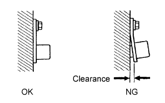
Check the camshaft position sensor.
OK Sensor is installed correctly.
NG
SECURELY REINSTALL SENSOR Click here
OK
-
-
INSPECT CAMSHAFT TIMING GEAR ASSEMBLY (TEETH)
-
Check the teeth of the camshaft timing gear assembly.
OK Teeth do not have any cracks or deformation.
NG
REPLACE CAMSHAFT TIMING GEAR ASSEMBLY Click here
OK
-
-
REPLACE CAMSHAFT POSITION SENSOR
-
Replace the camshaft position sensor Click here.
NEXT
-
-
CHECK WHETHER DTC OUTPUT RECURS
-
Connect the intelligent tester to the DLC3.
-
Turn the ignition switch to ON.
-
Turn the intelligent tester on.
-
Clear the DTCs.
-
Turn the ignition switch off and wait for at least 30 seconds.
-
Start the engine and idle it for 10 seconds or more.
-
Enter the following menus: Powertrain / Engine and ECT / DTC.
-
Read the DTCs.
Result Result Proceed to No DTC is output A P0340 is output B Tech Tips
If the engine does not start, replace the ECM.
B
REPLACE ECM Click here
A 
END
-