ECD SYSTEM, Diagnostic DTC:P0335
| DTC Code | DTC Name |
|---|---|
| P0335 | Crankshaft Position Sensor "A" Circuit |
DESCRIPTION
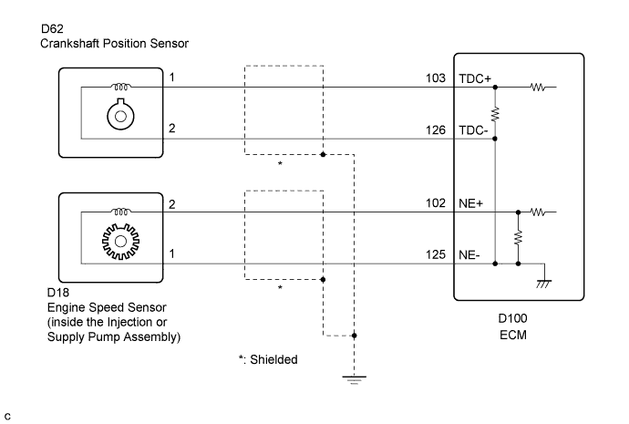
The engine speed sensor in the engine control system contains a signal plate and a pickup coil for the NE signal. The NE signal plate has 56 teeth and is mounted in the injection or supply pump assembly. The NE signal sensor generates 56 signals for every 2 engine revolutions. The ECM detects the engine speed and the cam lift position of the injection or supply pump assembly. The ECM uses the TDC and NE signals for injection timing control. The NE signal is also used for injection volume control.
| DTC No. | DTC Detection Condition | Trouble Area |
|---|---|---|
| P0335 | No NE signal to ECM for 0.5 seconds or more at 680 rpm or more. |
|
| No NE signal to ECM for 2.0 seconds or more during cranking. |
WIRING DIAGRAM
INSPECTION PROCEDURE
Tech Tips
Read freeze frame data using the GTS. Freeze frame data records the engine condition when malfunctions are detected. When troubleshooting, freeze frame data can help determine if the vehicle was moving or stationary, if the engine was warmed up or not, and other data from the time the malfunction occurred.
PROCEDURE
-
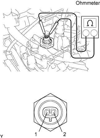
INSPECT ENGINE SPEED SENSOR
-
Check the engine speed sensor installation.
-
Disconnect the engine speed sensor connector.
-
Measure the resistance according to the value(s) in the table below.
Standard Resistance Tester Connection Condition Specified Condition 1 - 2 20°C (68°F) 205 to 255 Ω Tech Tips
The engine speed sensor is integrated with the injection or supply pump assembly. If the engine speed sensor is replaced, the injection or supply pump assembly must be replaced in whole.
NG 
REPLACE INJECTION OR SUPPLY PUMP ASSEMBLY Click here
OK 
-
-
CHECK HARNESS AND CONNECTOR (ECM - ENGINE SPEED SENSOR)
-
Disconnect the engine speed sensor connector.
-
Disconnect the ECM connector.
-
Measure the resistance according to the value(s) in the table below.
Standard Resistance Tester Connection Condition Specified Condition D18-2 - D100-102 (NE+) Always Below 1 Ω D18-1 - D100-125 (NE-) Always Below 1 Ω D18-2 or D100-102 (NE+) - Body ground Always 10 kΩ or higher D18-1 or D100-125 (NE-) - Body ground Always 10 kΩ or higher
NG
REPAIR OR REPLACE HARNESS OR CONNECTOR
OK 
REPLACE ECM Click here
-