VEHICLE STABILITY CONTROL SYSTEM, Diagnostic DTC:C1428

| DTC Code | DTC Name |
|---|---|
| C1428 | Motor Circuit Malfunction |
DESCRIPTION
This DTC is stored when the skid control ECU (brake actuator assembly) judges that an abnormality occurred in the circuit used to operate the pump motor.
| DTC No. | DTC Detection Condition | Trouble Area |
|---|---|---|
| C1428 | A malfunction occurs in the pump motor circuit. | Pump motor circuit |
WIRING DIAGRAM
Refer to DTC C146C Click here.
CAUTION / NOTICE / HINT
Note
-
When replacing the skid control ECU (brake actuator assembly), perform system variant learning and acceleration sensor zero point calibration Click here.
-
Inspect the fuses for circuits related to this system before performing the following procedure.
PROCEDURE
-
CHECK TERMINAL VOLTAGE (+BM TERMINAL)
-
Turn the ignition switch off.
-
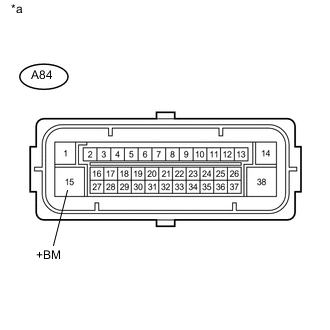
Text in Illustration *a Front view of wire harness connector
(to Skid Control ECU (Brake Actuator Assembly))
Make sure that there is no looseness at the locking part and the connecting part of the connector.
-
Disconnect the A84 skid control ECU (brake actuator assembly) connector.
-
Measure the voltage according to the value(s) in the table below.
Standard Voltage Tester Connection Condition Specified Condition A84-15 (+BM) - Body ground Always 11 to 14 V
NG 
REPAIR OR REPLACE HARNESS OR CONNECTOR (+BM CIRCUIT)
OK 
-
-
CHECK HARNESS AND CONNECTOR (GND2 TERMINAL)
-
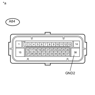
Text in Illustration *a Front view of wire harness connector
(to Skid Control ECU (Brake Actuator Assembly))
Measure the resistance according to the value(s) in the table below.
Standard Resistance Tester Connection Condition Specified Condition A84-38 (GND2) - Body ground Always Below 1 Ω
NG
REPAIR OR REPLACE HARNESS OR CONNECTOR (GND2 CIRCUIT)
OK
-
-
RECONFIRM DTC
-
Reconnect the A84 skid control ECU (brake actuator assembly) connector.
-
Clear the DTCs Click here.
-
Turn the ignition switch off.
-
Start the engine.
-
Perform a road test.
-
Check if the same DTC is output Click here.
Result Result Proceed to DTC C1428 is not output. A DTC C1428 is output. B
A
USE SIMULATION METHOD TO CHECK Click here
B
REPLACE BRAKE ACTUATOR ASSEMBLY Click here
-