VEHICLE STABILITY CONTROL SYSTEM, Diagnostic DTC:C146E

| DTC Code | DTC Name |
|---|---|
| C146E | Open in ABS Solenoid Relay Circuit |
DESCRIPTION
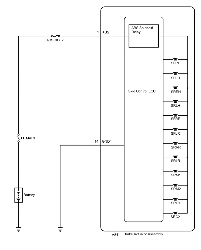
The ABS solenoid relay is built into the skid control ECU in the brake actuator assembly. The ABS solenoid relay supplies power to the ABS and TRC solenoids. The skid control ECU detects a solenoid relay malfunction by performing a self check and relay operation check.
| DTC No. | DTC Detection Condition | Trouble Area |
|---|---|---|
| C146E | Either of the following is detected:
|
|
WIRING DIAGRAM
CAUTION / NOTICE / HINT
Note
-
When replacing the skid control ECU (brake actuator assembly), perform system variant learning and acceleration sensor zero point calibration Click here.
-
Inspect the fuses for circuits related to this system before performing the following procedure.
Tech Tips
When C1241 and/or C1417 is output together with C146E, inspect and repair the trouble areas indicated by C1241 and/or C1417 first (See page for C1241 and/or Click here for C1417).
PROCEDURE
-
CHECK TERMINAL VOLTAGE (+BS TERMINAL)
-
Turn the ignition switch off.
-
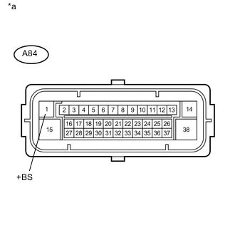
Text in Illustration *a Front view of wire harness connector
(to Skid Control ECU (Brake Actuator Assembly))
Make sure that there is no looseness at the locking part and the connecting part of the connector.
-
Disconnect the A84 skid control ECU (brake actuator assembly) connector.
-
Measure the voltage according to the value(s) in the table below.
Standard Voltage Tester Connection Condition Specified Condition A84-1 (+BS) - Body ground Always 11 to 14 V
NG 
REPAIR OR REPLACE HARNESS OR CONNECTOR (+BS CIRCUIT)
OK 
-
-
CHECK HARNESS AND CONNECTOR (GND1 TERMINAL)
-
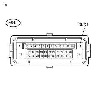
Text in Illustration *a Front view of wire harness connector
(to Skid Control ECU (Brake Actuator Assembly))
Measure the resistance according to the value(s) in the table below.
Standard Resistance Tester Connection Condition Specified Condition A84-14 (GND1) - Body ground Always Below 1 Ω
NG
REPAIR OR REPLACE HARNESS OR CONNECTOR (GND1 CIRCUIT)
OK
-
-
RECONFIRM DTC
Tech Tips
-
This DTC is stored when a problem is identified in the skid control ECU (brake actuator assembly).
-
The solenoid circuits are located in the skid control ECU (brake actuator assembly).
Therefore, solenoid circuit inspection and solenoid unit inspection cannot be performed.
Be sure to check if the DTC is output again before replacing the skid control ECU (brake actuator assembly).
-
Reconnect the A84 skid control ECU (brake actuator assembly) connector.
-
Clear the DTCs Click here.
-
Turn the ignition switch off.
-
Start the engine.
-
Drive the vehicle at a speed of 50 km/h (31 mph) or more for 30 seconds or more.
-
Check if the same DTC is output Click here.
Result Result Proceed to DTC C146E is not output. A DTC C146E is output. B Tech Tips
-
The skid control ECU (brake actuator assembly) performs self diagnosis of the solenoid circuit after the ignition switch is turned to ON.
-
If the normal system code is output (no DTCs are output), slightly jiggle the connectors, wire harnesses, and fuses of the skid control ECU (brake actuator assembly).
-
If any DTCs are output while jiggling a connector or wire harness of the skid control ECU (brake actuator assembly), inspect and repair the connector or wire harness.
-
If no DTCs were output when reconfirming DTCs, checking for intermittent problems is necessary because it is suspected that the original DTCs were stored due to the poor connection of a connector terminal.
-
A
USE SIMULATION METHOD TO CHECK Click here
B
REPLACE BRAKE ACTUATOR ASSEMBLY Click here
-