MANUAL TRANSAXLE ASSEMBLY REMOVAL
PROCEDURE
-
PRECAUTION
Note
After turning the ignition switch off, waiting time may be required before disconnecting the cable from the battery terminal. Therefore, make sure to read the disconnecting the cable from the battery terminal notice before proceeding with work Click here.
-
DISCONNECT NEGATIVE BATTERY TERMINAL
Note
When disconnecting the cable, some systems need to be initialized after the cable is reconnected Click here.
-
REMOVE FRONT WIPER MOTOR AND LINK ASSEMBLY
-
REMOVE OUTER COWL TOP PANEL
-
REMOVE FRONT LOWER BUMPER ABSORBER
-
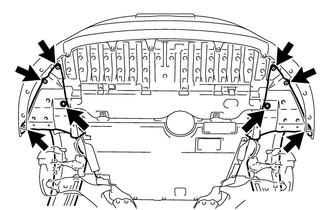
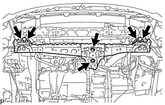
Remove the 6 screws and 2 bolts.
Tech Tips
Pull down the fender liner so that the front lower bumper absorber can be in the next step.
-
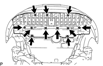
Remove the 3 screws, 8 bolts and front lower bumper absorber.
-
-
REMOVE NO. 1 ENGINE UNDER COVER
-
REMOVE NO. 2 ENGINE UNDER COVER
-
REMOVE STARTER ASSEMBLY
-
REMOVE EXHAUST PIPE ASSEMBLY
-
REMOVE REAR ENGINE UNDER COVER LH
-
REMOVE REAR ENGINE UNDER COVER RH
-
DRAIN MANUAL TRANSAXLE OIL
-
REMOVE DRIVE SHAFT ASSEMBLY
-
DRAIN ENGINE COOLANT
-
REMOVE NO. 1 ENGINE COVER
-
REMOVE AIR CLEANER CAP SUB-ASSEMBLY WITH AIR CLEANER HOSE ASSEMBLY
-
REMOVE AIR CLEANER FILTER ELEMENT SUB-ASSEMBLY
-
REMOVE AIR CLEANER CASE SUB-ASSEMBLY
-
REMOVE AIR CLEANER BRACKET
-
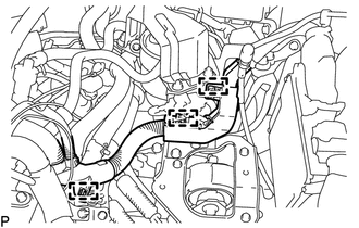
Disconnect the 3 clamps and wire harness.
-
Remove the 5 bolts and air cleaner bracket.
-
-
REMOVE WIRE HARNESS
-
REMOVE NO. 4 WATER BY-PASS HOSE
-
DISCONNECT COMPRESSOR OUTLET ELBOW
-
DISCONNECT INTERCOOLER AIR HOSE
-
REMOVE NO. 1 AIR TUBE ASSEMBLY
-
DISCONNECT TRANSMISSION CONTROL CABLE ASSEMBLY
-
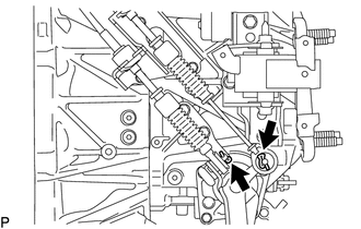
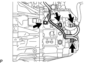
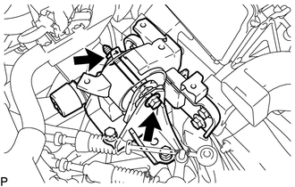
Remove the 2 clips and disconnect the 2 cables from the manual transaxle assembly.
-
Remove the 2 clips and disconnect the 2 cables from the control cable bracket.
-
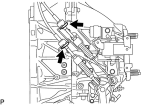
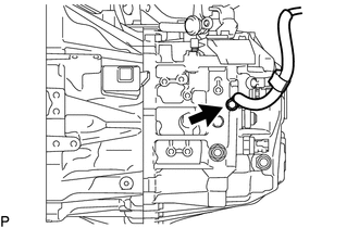
Remove the bolt and disconnect the bracket of the transmission control cable assembly.
-
-
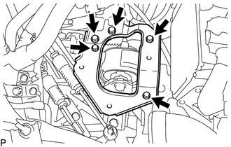
REMOVE NO. 1 CLUTCH HOUSING COVER
-
Remove the 2 bolts and No. 1 clutch housing cover.
-
-
REMOVE NO. 2 MANIFOLD STAY
-
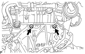
Using an E14 "TORX" socket wrench, remove the 2 bolts from the manual transaxle assembly.
-
Remove the nut and No. 2 manifold stay.
-
-
DISCONNECT CLUTCH RELEASE CYLINDER ASSEMBLY
-
DISCONNECT ENGINE WIRE
-
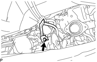
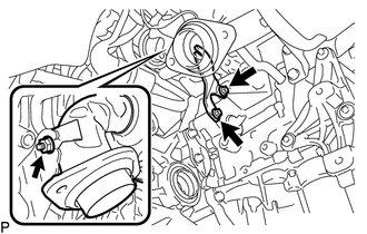
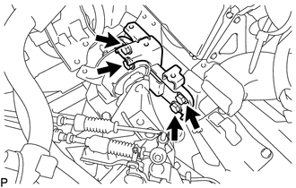
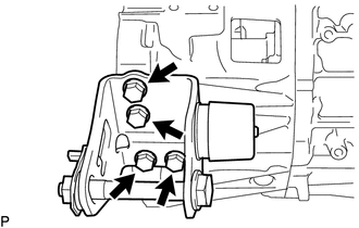
Remove the bolt and disconnect the ground cable.
-
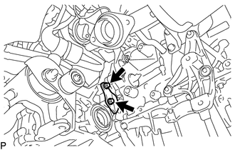
Disconnect the back-up light switch connector, neutral position switch connector, 2 bolts and engine wire.
-
-
LOOSEN ENGINE AND TRANSAXLE CONNECTING BOLT
-
Manual transaxle upper side:
Using an E14 "TORX" socket wrench, loosen the 2 bolts.
-
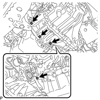
Manual transaxle lower side:
Loosen the 4 bolts.
-
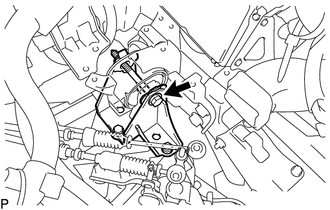
Engine mounting insulator side:
Loosen the bolt.
-
-
REMOVE FRONT SUSPENSION MEMBER
-
SUPPORT MANUAL TRANSAXLE ASSEMBLY
-
Support the manual transaxle assembly with a transmission jack and tie down band so that it is stable.
-
-
REMOVE FRONT CROSSMEMBER SUB-ASSEMBLY
-
Remove the 6 bolts and front crossmember sub-assembly.
-
-
REMOVE FRONT ENGINE MOUNTING INSULATOR
-
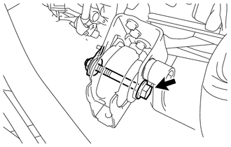
Remove the through bolt, nut and front engine mounting insulator.
-
-
REMOVE MANUAL TRANSAXLE ASSEMBLY
Note
-
As there is very little space around the manual transaxle assembly, be extremely careful that the body, clutch pipe line and radiator cooling fan do not interfere with the manual transaxle assembly when removing the transaxle.
-
When removing the manual transaxle assembly, it is necessary to move the engine assembly and manual transaxle assembly up and down, and back and forth. Therefore, continually confirm that the parts are properly supported and stable while performing this step.
-
Remove the nut and through bolt, and then disconnect the engine mounting insulator LH from the engine mount bracket LH.
-
Lower the transmission jack a little at a time. Slightly tilt the engine assembly and manual transaxle assembly.
Tech Tips
Lower the engine assembly and manual transaxle assembly to a position where the engine mounting insulator LH can be removed.
-
Remove the 4 bolts and engine mount insulator LH.
-
Remove the 4 bolts and engine mounting bracket LH.
Note
Make sure to clean the bolts and bolt holes after removing the transmission.
-
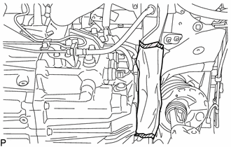
Use a cloth, etc. to protect the clutch pipe line in the area indicated in the illustration.
-
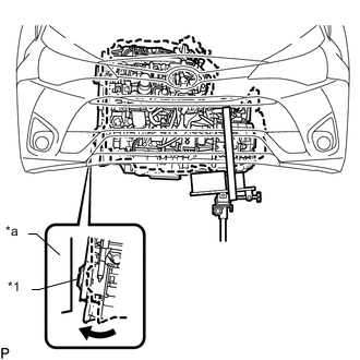
Text in Illustration *1 Crankshaft Damper Sub-assembly *a Body Lower the transmission jack a little at a time. Slightly tilt the engine assembly and manual transaxle assembly.
Note
Be careful that the body and crankshaft damper sub-assembly do not interfere with each other.
-
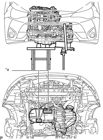
Text in Illustration *a Engine Support Point Support the engine assembly with an engine lifter as shown in the illustration so that it is stable.
-
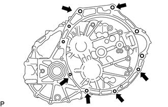
Remove the 6 bolts shown in the illustration.
-
While making sure that the clutch pipe line does not interfere with the manual transaxle assembly, slowly disconnect the manual transaxle assembly from the engine assembly until the input shaft is clear of the diaphragm spring of the clutch cover.
-
Slowly lower the transmission jack and remove the manual transaxle assembly.
-
-
REMOVE REAR ENGINE MOUNTING INSULATOR
-
REMOVE FRONT ENGINE MOUNTING BRACKET
-
Remove the 4 bolts and front engine mounting bracket.
-
-
REMOVE REAR ENGINE MOUNTING BRACKET
-
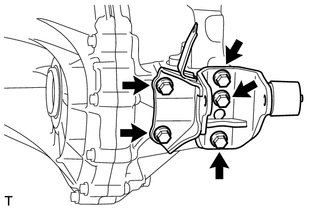
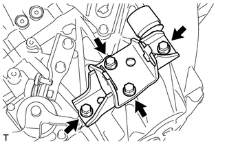
Remove the 5 bolts and rear engine mounting bracket.
-