FUEL PUMP REMOVAL

PROCEDURE
-
REMOVE REAR BENCH TYPE SEAT CUSHION ASSEMBLY
-
for Sedan: Click here
-
for Wagon: Click here
-
-
REMOVE REAR FLOOR SERVICE HOLE COVER
-
Remove the butyl tape and rear floor service hole cover.
-
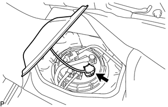
Disconnect the fuel suction with pump and gauge tube assembly connector.
-
-
DISCONNECT FUEL TANK RETURN TUBE SUB-ASSEMBLY
-
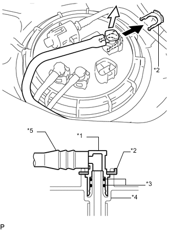
Text in Illustration *1 Fuel Tube Joint *2 Tube Joint Clip *3 O-Ring *4 Fuel Suction with Pump and Gauge Tube Assembly *5 Nylon Tube Remove the tube joint clip and pull out the fuel tank return tube sub-assembly.
Note
-
Remove any dirt and foreign matter on the fuel tube joint before performing this step.
-
Do not scratch or allow any foreign matter to adhere to the parts when disconnecting them as the fuel tube joint contains the O-rings that seal the plug.
-
Perform this step by hand. Do not use any tools.
-
Do not forcibly bend or twist the nylon tube.
-
Protect the disconnected part by covering it with a plastic bag after disconnecting the fuel tube.
-
-
-
DISCONNECT FUEL TANK MAIN TUBE SUB-ASSEMBLY
-
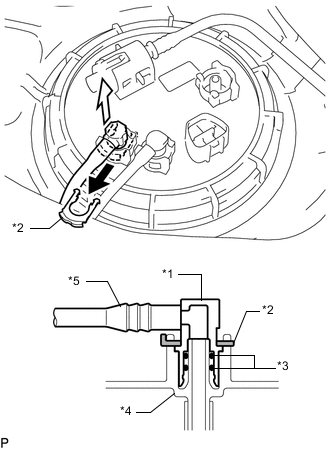
Text in Illustration *1 Fuel Tube Joint *2 Tube Joint Clip *3 O-Ring *4 Fuel Suction with Pump and Gauge Tube Assembly *5 Nylon Tube Remove the tube joint clip and pull out the fuel tank main tube sub-assembly.
Note
-
Remove any dirt and foreign matter on the fuel tube joint before performing this step.
-
Do not scratch or allow any foreign matter to adhere to the parts when disconnecting them as the fuel tube joint contains the O-rings that seal the plug.
-
Perform this step by hand. Do not use any tools.
-
Do not forcibly bend or twist the nylon tube.
-
Protect the disconnected part by covering it with a plastic bag after disconnecting the fuel tube.
-
-
-
DISCONNECT NO. 2 FUEL TANK MAIN TUBE SUB-ASSEMBLY (w/ Combustion Type Power Heater)
-
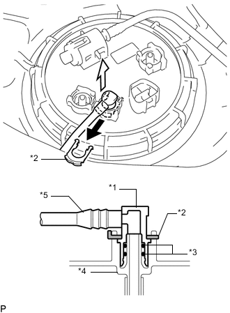
Text in Illustration *1 Fuel Tube Joint *2 Tube Joint Clip *3 O-Ring *4 Fuel Suction with Pump and Gauge Tube Assembly *5 Nylon Tube Remove the tube joint clip and pull out the No. 2 fuel tank main tube sub-assembly.
Note
-
Remove any dirt and foreign matter on the fuel tube joint before performing this step.
-
Do not scratch or allow any foreign matter to adhere to the parts when disconnecting them as the fuel tube joint contains the O-rings that seal the plug.
-
Perform this step by hand. Do not use any tools.
-
Do not forcibly bend or twist the nylon tube.
-
Protect the disconnected part by covering it with a plastic bag after disconnecting the fuel tube.
-
-
-
REMOVE TANK SUCTION TUBE SUPPORT
-
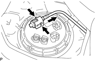
Press on the tabs from both sides of the fuel tube clamp.
-
Pull the tank suction tube support in the direction indicated by the arrow in the illustration.
-
Detach the 2 claws and remove the tank suction tube support.
-
-
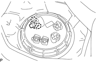
REMOVE FUEL PUMP GAUGE RETAINER
Note
Before performing these procedures, first cover the connector and fuel tube joint of the fuel suction with pump and gauge tube assembly with vinyl tape and then clean any dirt and foreign matter in order to prevent contamination of the fuel system.
-
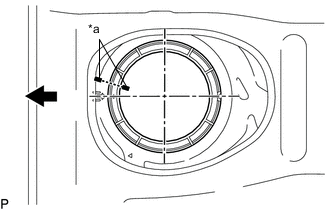
Text in Illustration *a Co-rotation Prevention Check Mark 
Front Side of Vehicle Apply a co-rotation prevention check mark to the fuel suction with pump and gauge tube assembly and vehicle body.
Note
-
The fuel suction with pump and gauge tube assembly has 2 protrusions that engage with 2 notches on the fuel tank assembly to ensure correct alignment and to prevent the fuel suction with pump and gauge tube assembly from turning during installation and removal of the fuel pump gauge retainer.
-
If the fuel pump gauge retainer is turned with the fuel suction with pump and gauge tube assembly misaligned, the fuel suction with pump and gauge tube assembly will turn with the fuel pump gauge retainer and may be damaged.
-
Make sure to apply a co-rotation prevention check mark to prevent the fuel suction with pump and gauge tube assembly from co-rotating.
-
-
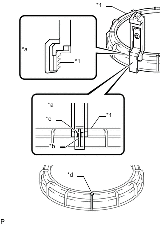
Text in Illustration *1 Fuel Pump Gauge Retainer *a SST (Claw Set) *b Rib *c Cutout *d SST (Claw Set) Incorrect Installation Point (Rotational Start Point Mark of Fuel Pump Gauge Retainer) Install SST to the fuel pump gauge retainer.
-
Set 4 SST (claw set) to the fuel pump gauge retainer.
- SST
- 09808-14031 ( 09808-01080, 09808-01090, 09808-01100 )
Note
-
Align the notch of SST (claw set) with the protrusion of the fuel pump gauge retainer.
-
Do not place SST on the rotational start point mark of the fuel pump gauge retainer, otherwise SST (claw set) cannot be set correctly.
-
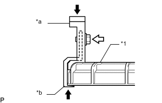
Text in Illustration *1 Fuel Pump Gauge Retainer *a SST (Claw Set) *b Hook Press 
SST (Bolt) While firmly pressing the claw of SST against the rib of the fuel pump gauge retainer, tighten the bolt.
-
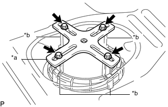
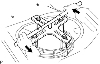
Text in Illustration *a SST (Plate) *b SST (Claw Set) SST (Bolt) Temporarily install SST (plate) to SST (claw set) with 4 SST (bolt).
- SST
- 09808-14031 ( 09808-01090, 09808-01030 )
-
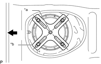
Text in Illustration *a Center Point of Fuel Pump Gauge Retainer *b SST (Plate) Front Side of Vehicle Adjust the position of SST (claw set) so that the hole in SST (plate) for installing SST (handle) is in the center of the fuel pump gauge retainer.
-
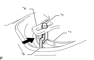
Text in Illustration *1 Fuel Pump Gauge Retainer *a SST (Plate) *b SST (Claw Set) *c SST (Bolt) Press Press SST (claw set) against the rib of the fuel pump gauge retainer and tighten SST (bolt).
-
Text in Illustration *a SST (Plate) *b SST (Handle) Loosen Install SST (handle) to SST (plate).
- SST
- 09808-14031 ( 09808-01010, 09808-01020 )
-
-
Slowly loosen the fuel pump gauge retainer by approximately 90°.
Note
-
Do not spin SST too fast or use an impact wrench as this may result in damage to components.
-
Do not use any tools other than SST, such as a screwdriver, etc.
-
Do not use excessive force when pressing down on SST, as the fuel pump gauge retainer will place excessive force on the fuel suction tube assembly with pump and gauge and be difficult to remove, and parts may be damaged.
-
-
While one person loosens the fuel pump gauge retainer, have another person press down the rising fuel suction with pump and gauge tube assembly, securely insert the protrusion of the fuel suction with pump and gauge tube assembly into the groove of the fuel tank assembly, and then remove the fuel pump gauge retainer while making sure that the fuel suction with pump and gauge tube assembly is properly aligned.
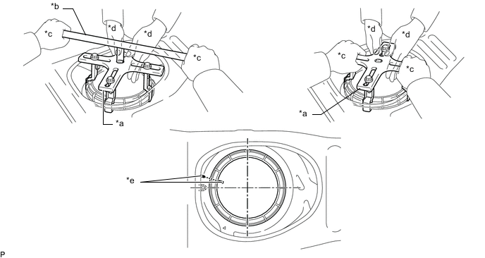
Text in Illustration *a SST (Plate) *b SST (Handle) *c Person in Change of Loosening *d Person in Charge of Pressing Down *e Co-rotation Prevention Check Mark - - Note
-
The fuel suction with pump and gauge tube assembly is pressed against the underside of the fuel tank assembly by a spring, and the constant upward pressure applied by this spring causes the fuel suction with pump and gauge tube assembly to rise up.
-
If the fuel pump gauge retainer is turned while the fuel suction with pump and gauge tube assembly and fuel tank assembly are not correctly aligned, the fuel suction with pump and gauge tube assembly will move with the fuel pump gauge retainer, and the fuel suction with pump and gauge tube assembly and fuel tank assembly may both be damaged.
-
Do not rotate the fuel pump gauge retainer when the co-rotation prevention check mark is out of place.
-
Be careful not to bend the arm of the fuel sender gauge assembly.
-
-
-
REMOVE FUEL SUCTION WITH PUMP AND GAUGE TUBE ASSEMBLY
-
Remove the fuel suction with pump and gauge tube assembly from the fuel tank assembly.
Note
Make sure that the fuel sender gauge assembly arm does not bend.
-
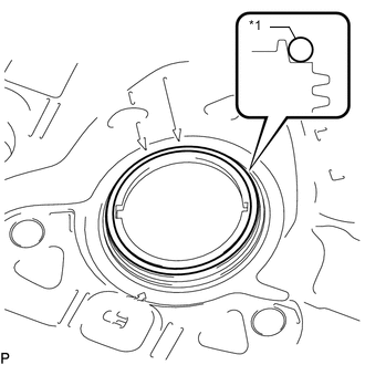
Text in Illustration *1 Gasket Remove the gasket from the fuel tank assembly.
-
-
REMOVE FUEL SENDER GAUGE ASSEMBLY