FUEL FILTER REPLACEMENT

PROCEDURE
-
REMOVE NO. 1 ENGINE COVER
-
REMOVE AIR CLEANER CAP SUB-ASSEMBLY
-
REMOVE AIR CLEANER FILTER ELEMENT SUB-ASSEMBLY
-
REMOVE AIR CLEANER CASE SUB-ASSEMBLY
-
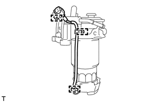
REMOVE FUEL FILTER ASSEMBLY (w/o Combustion Type Power Heater)
-
Disconnect the 4 fuel hoses.
-
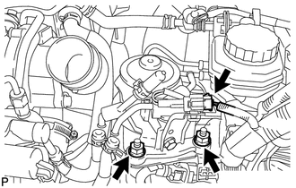
Disconnect the level warning switch connector.
-
Remove the 2 nuts and fuel filter assembly.
-
-
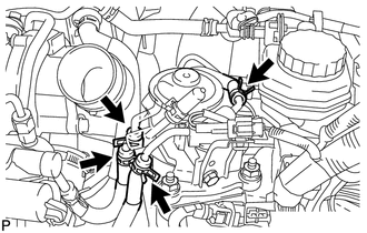
REMOVE FUEL FILTER ASSEMBLY (w/ Combustion Type Power Heater)
-
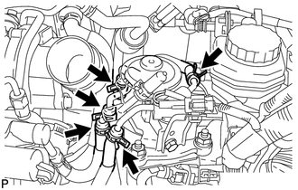
Disconnect the 5 fuel hoses.
-
Disconnect the level warning switch connector.
-
Remove the 2 nuts and fuel filter assembly.
-
-
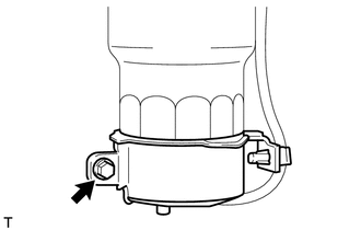
DRAIN FUEL
-
Loosen the drain bolt and drain the fuel from the fuel filter.
-
-
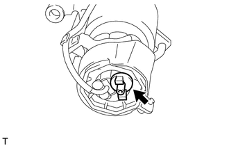
REMOVE FUEL FILTER GASKET
-
Detach the 3 harness clamps.
-
Remove the bolt, filter cover and filter gasket.
-
-
REMOVE LEVEL WARNING SWITCH
-
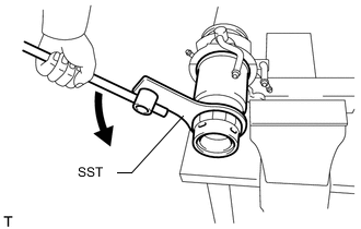
REMOVE FUEL FILTER ELEMENT SUB-ASSEMBLY
-
Using SST, remove the fuel filter element.
- SST
- 09228-64010
-
-
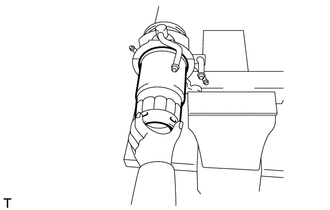
INSTALL FUEL FILTER ELEMENT SUB-ASSEMBLY
-
Check and clean the installation surface of the fuel filter.
-
Apply fuel to the gasket of a new fuel filter element.
-
Lightly screw the fuel filter element into place, and tighten it until the gasket comes into contact with the seat.
-
Tighten the fuel filter element an additional 3/4 turn by hand.
-
-
INSTALL LEVEL WARNING SWITCH
-
INSTALL FUEL FILTER GASKET
-
Install the filter gasket and filter cover to the fuel filter assembly.
-
Tighten the bolt.
- Torque:
- 3.4 N*m { 35 kgf*cm, 30 in.*lbf }
-
Attach the 3 harness clamps.
-
-
INSTALL FUEL FILTER ASSEMBLY (w/ Combustion Type Power Heater)
-
Install the fuel filter assembly with the 2 nuts.
- Torque:
- 18 N*m { 178 kgf*cm, 13 ft.*lbf }
-
Connect the level warning switch connector.
-
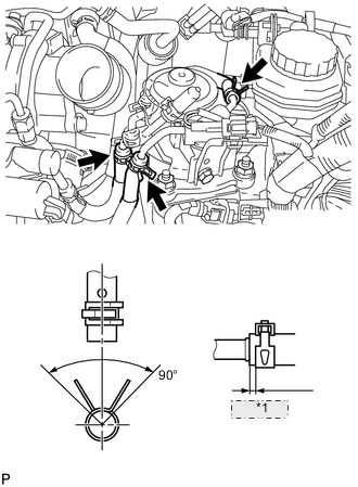
*1 1 to 5 mm Connect the No. 1 fuel hose, No. 2 fuel hose and No. 3 fuel hose.
Tech Tips
-
Align the alignment marks and connect the hose.
-
Align the claws of the clamp with the hose alignment mark as shown in the illustration.
-
Position the clamp so that the distance from the end of the hose is 1 to 5 mm (0.0394 to 0.197 in.).
-
-
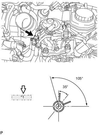
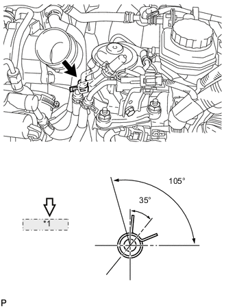
*1 Front Side of Vehicle Connect the No. 4 fuel hose.
Tech Tips
Make sure the direction of the hose clamp is as shown in the illustration.
-
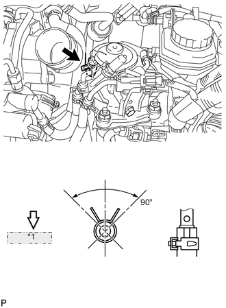
*1 Front Side of Vehicle Connect the heater fuel hose.
Tech Tips
-
Align the alignment marks and connect the hose.
-
Make sure the direction of the hose clamp is as shown in the illustration.
-
-
-
INSTALL FUEL FILTER ASSEMBLY (w/o Combustion Type Power Heater)
-
Install the fuel filter assembly with the 2 nuts.
- Torque:
- 18 N*m { 178 kgf*cm, 13 ft.*lbf }
-
Connect the level warning switch connector.
-
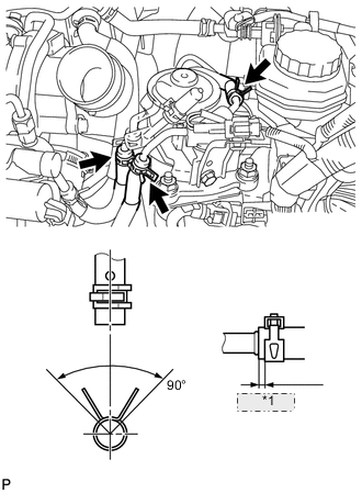
*1 1 to 5 mm Connect the No. 1 fuel hose, No. 2 fuel hose and No. 3 fuel hose.
Tech Tips
-
Align the alignment marks and connect the hose.
-
Align the claws of the clamp with the hose alignment mark as shown in the illustration.
-
Position the clamp so that the distance from the end of the hose is 1 to 5 mm (0.0394 to 0.197 in.).
-
-
*1 Front Side of Vehicle Connect the No. 4 fuel hose.
Tech Tips
Make sure the direction of the hose clamp is as shown in the illustration.
-
-
INSTALL AIR CLEANER CASE SUB-ASSEMBLY
-
INSTALL AIR CLEANER FILTER ELEMENT SUB-ASSEMBLY
-
INSTALL AIR CLEANER CAP SUB-ASSEMBLY
-
BLEED AIR FROM FUEL SYSTEM
-
INSPECT FOR FUEL LEAK
-
INSTALL NO. 1 ENGINE COVER