FUEL SENDER GAUGE ASSEMBLY REMOVAL

PROCEDURE
-
REMOVE REAR SEAT CUSHION ASSEMBLY
-
for Sedan: Click here
-
for Wagon: Click here
-
-
REMOVE REAR FLOOR SERVICE HOLE COVER
-
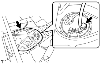
Remove the butyl tape and rear floor service hole cover.
-
Disconnect the fuel sender gauge assembly connector.
-
-
DISCONNECT FUEL TANK MAIN TUBE SUB-ASSEMBLY
-
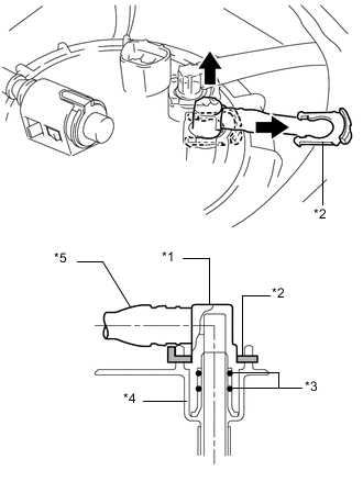
Text in Illustration *1 Fuel Tank Main Tube Sub-assembly *2 Tube Joint Clip *3 O-Ring *4 Fuel Tank Vent Tube Sub-assembly *5 Nylon Tube Remove the tube joint clip and pull out the fuel tank main tube sub-assembly.
Note
-
Remove any dirt and foreign matter on the fuel tube joint before performing this step.
-
Do not scratch or allow any foreign matter to adhere to the parts when disconnecting them as the fuel tube joint contains the O-rings that seal the plug.
-
Perform this step by hand. Do not use any tools.
-
Do not forcibly bend or twist the nylon tube.
-
Protect the disconnected part by covering it with a plastic bag after disconnecting the fuel tank main tube sub-assembly.
-
-
-
DISCONNECT FUEL TANK RETURN TUBE SUB-ASSEMBLY
-
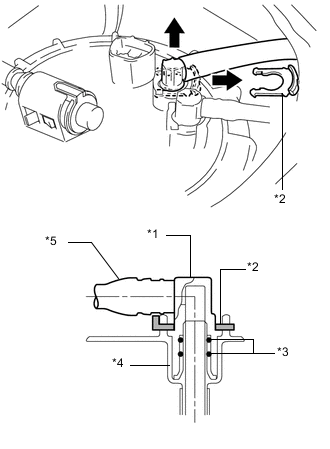
Text in Illustration *1 Fuel Tank Return Tube Sub-assembly *2 Tube Joint Clip *3 O-Ring *4 Fuel Tank Vent Tube Sub-assembly *5 Nylon Tube Remove the tube joint clip and pull out the fuel tank return tube sub-assembly.
Note
-
Remove any dirt and foreign matter on the fuel tube joint before performing this step.
-
Do not scratch or allow any foreign matter to adhere to the parts when disconnecting them as the fuel tube joint contains the O-rings that seal the plug.
-
Perform this step by hand. Do not use any tools.
-
Do not forcibly bend or twist the nylon tube.
-
Protect the disconnected part by covering it with a plastic bag after disconnecting the fuel tank return tube sub-assembly.
-
-
-
REMOVE TANK SUCTION TUBE SUPPORT
-
Press on the tabs from both sides of the fuel tube clamp.
-
Pull the tank suction tube support in the direction indicated by the arrow in the illustration.
-
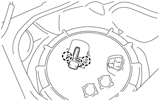
Detach the 2 claws and remove the tank suction tube support.
-
-
REMOVE FUEL PUMP GAUGE RETAINER
CAUTION:
Due to swelling of the fuel tank assembly, the tightening torque of the fuel pump gauge retainer may be as high as 200 N*m (2039 kgf*cm, 148 ft.*lbf), so perform the procedure with at least 2 people.
Note
Before performing these procedures, first cover the connectors and tube joints of the fuel tank vent tube sub-assembly with vinyl tape and then clean away any mud or other substances that may be adhering in order to prevent foreign matter from contaminating the fuel system.
-
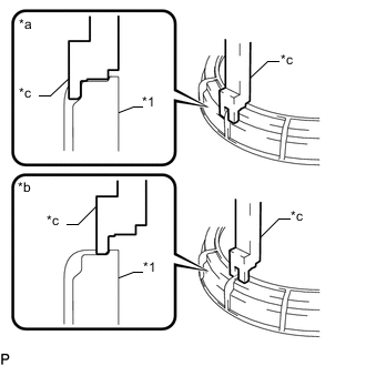
Text in Illustration *1 Fuel Pump Gauge Retainer *a CORRECT *b INCORRECT *c SST (Claw) Temporarily install SST (plate) and SST (claw) to the fuel pump gauge retainer.
- SST
- 09808-14030
- 09808-01070 ( 09808-01010, 09808-01020, 09808-01030, 09808-01050 )
Note
Install SST (claw) to the correct location.
-
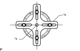
Text in Illustration *a Center Point of Fuel Pump Gauge Retainer *b SST (Plate) Adjust the position of SST (claw) so that the hole in SST (plate) for installing SST (handle) is in the center of the fuel pump gauge retainer.
-
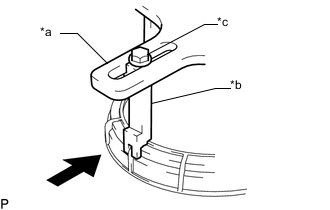
Text in Illustration *a SST (Plate) *b SST (Claw) *c SST (Bolt) 
Press Press SST (claw) against the rib of the fuel pump gauge retainer and tighten SST (bolt).
-
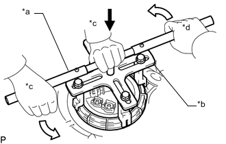
Text in Illustration *a SST (Handle) *b SST (Plate) *c Worker A *d Worker B Hold Down 
Slowly Rotate Install SST (handle) to SST (plate).
-
To make sure SST does not separate from the fuel pump gauge retainer, one person should hold down the center of SST from above while at the same time both people slowly rotate SST (handle), and slowly loosen the fuel pump gauge retainer by approximately 90°.
Note
-
Be careful not to apply excessive downward force to SST, as this may damage the fuel tank vent tube sub-assembly or fuel tank assembly.
-
Turning SST at an angle may cause it to slip off of the fuel pump gauge retainer, so make sure SST is horizontal when turning it.
-
To prevent damage to parts, do not turn SST too vigorously.
-
If SST slips off of the fuel pump gauge retainer, loosen SST (bolt) and install SST again.
-
-
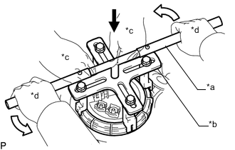
Text in Illustration *a SST (Handle) *b SST (Plate) *c Worker A *d Worker B Press Down Slowly Rotate While one person presses down to prevent the fuel pump gauge retainer and fuel tank vent tube sub-assembly from rotating together, the other person should slowly rotate SST (handle) and remove the fuel pump gauge retainer from the fuel tank assembly.
CAUTION:
Make sure not to pinch your hands with SST.
Note
If the fuel pump gauge retainer is turned while the fuel tank vent tube sub-assembly and fuel tank assembly are not fully engaged, the fuel tank vent tube sub-assembly will move with the fuel pump gauge retainer, and the fuel tank vent tube sub-assembly and the fuel tank assembly will both be damaged.
-
-
REMOVE FUEL TANK VENT TUBE SUB-ASSEMBLY
-
Remove the fuel tank vent tube sub-assembly from the fuel tank assembly.
Note
Make sure that the fuel sender gauge assembly arm does not bend.
-
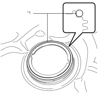
Text in Illustration *1 Gasket Remove the gasket from the fuel tank assembly.
-
-
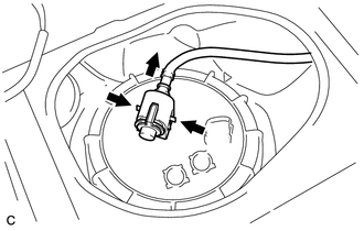
REMOVE FUEL SENDER GAUGE ASSEMBLY
-
Disconnect the fuel sender gauge assembly connector.
-
Detach the wire harness clamp.
Note
Do not damage the wire harness.
-
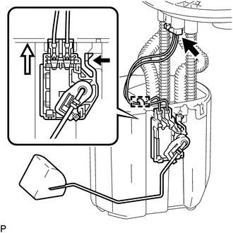
Release the lock as shown in the illustration and slide the fuel sender gauge assembly to remove it.
-