ENGINE ASSEMBLY REMOVAL

PROCEDURE
-
INSPECT DRIVE AWAY RELEASE FUNCTION (for Manual Transaxle)
-
PLACE FRONT WHEELS FACING STRAIGHT AHEAD
-
PRECAUTION
Note
After turning the ignition switch off, waiting time may be required before disconnecting the cable from the battery terminal. Therefore, make sure to read the disconnecting the cable from the battery terminal notice before proceeding with work Click here.
-
DISCONNECT CABLE FROM NEGATIVE BATTERY TERMINAL
Note
When disconnecting the cable, some systems need to be initialized after the cable is reconnected Click here.
-
DISCONNECT CABLE FROM POSITIVE BATTERY TERMINAL
-
REMOVE FRONT WHEEL
-
REMOVE FRONT WIPER MOTOR AND LINK ASSEMBLY
-
REMOVE DIFFERENTIAL PRESSURE SENSOR ASSEMBLY
-
REMOVE OUTER COWL TOP PANEL SUB-ASSEMBLY
-
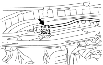
Disconnect the connector and detach the harness clamp.
-
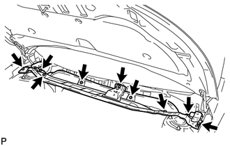
Remove the 9 bolts and outer cowl top panel.
-
-
REMOVE FRONT BUMPER COVER (for Automatic Transaxle)
-
REMOVE NO. 1 ENGINE COVER
-
REMOVE RADIATOR SUPPORT OPENING COVER
-
REMOVE FRONT LOWER BUMPER ABSORBER
-
REMOVE NO. 1 ENGINE UNDER COVER
-
REMOVE CENTER NO. 4 ENGINE UNDER COVER
-
Remove the 2 clips and center No. 4 engine under cover.
-
-
REMOVE NO. 2 ENGINE UNDER COVER
-
REMOVE REAR ENGINE UNDER COVER RH
-
Remove the 5 clips and rear engine under cover RH.
-
-
REMOVE REAR ENGINE UNDER COVER LH
-
Remove the 5 clips and rear engine under cover LH.
-
-
DRAIN ENGINE COOLANT
-
DRAIN ENGINE OIL
-
DRAIN MANUAL TRANSAXLE OIL (for Manual Transaxle)
-
DRAIN AUTOMATIC TRANSAXLE FLUID (for Automatic Transaxle)
-
REMOVE FRONT EXHAUST PIPE ASSEMBLY
-
REMOVE BATTERY CLAMP SUB-ASSEMBLY
-
REMOVE BATTERY INSULATOR
-
REMOVE BATTERY
-
REMOVE BATTERY TRAY
-
REMOVE BATTERY CARRIER
-
REMOVE RADIATOR ASSEMBLY (for Automatic Transaxle)
-
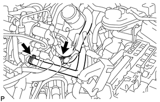
REMOVE OIL COOLER TUBE SUB-ASSEMBLY (for Automatic Transaxle)
-
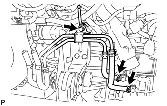
Disconnect the 2 hoses.
-
Remove the bolt and oil cooler tube.
-
-
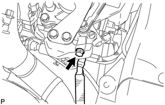
DISCONNECT NO. 2 VACUUM TRANSMITTING HOSE ASSEMBLY
-
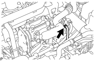
Disconnect the No. 2 vacuum transmitting hose from the intake manifold.
-
-
REMOVE NO. 3 AIR HOSE
-
REMOVE AIR CLEANER CAP SUB-ASSEMBLY
-
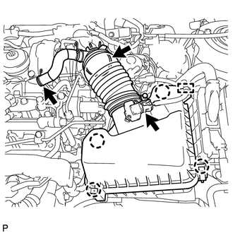
Detach the clamp and disconnect the mass air flow meter connector.
-
Disconnect the No. 2 ventilation hose.
-
Disconnect the air cleaner hose.
-
Detach the 4 clamps and remove the air cleaner cap.
-
-
REMOVE AIR CLEANER FILTER ELEMENT SUB-ASSEMBLY
-
REMOVE AIR CLEANER CASE
-
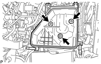
Remove the 3 bolts and air cleaner case.
-
-
REMOVE FUEL FILTER ASSEMBLY (w/o Combustion Type Power Heater)
-
REMOVE FUEL FILTER ASSEMBLY (w/ Combustion Type Power Heater)
-
REMOVE FUEL FILTER SUPPORT
-
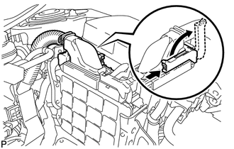
Raise the lever while pushing the lock on the lever, and disconnect the ECM connector.
Note
After disconnecting the connector, make sure that dirt, water or other foreign matter does not contact the connecting parts of the connector.
-
Disconnect the connector.
-
Detach the 2 clamps and disconnect the engine wire.
-
Remove the bolt and disconnect the glow relay.
-
Detach the 2 clamps and disconnect the wire harness.
-
Remove the 3 bolts and fuel filter support.
-
-
REMOVE AIR CLEANER BRACKET
-
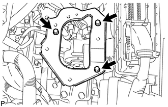
Remove the 3 bolts and air cleaner bracket.
-
-
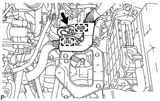
DISCONNECT HOSES AND CONNECTORS
-
Remove the engine room No. 1 relay block cover.
-
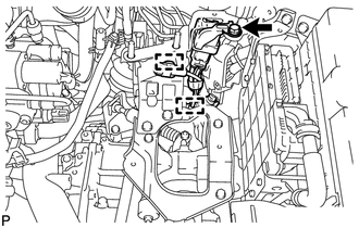
Disconnect the current sensor connector.
-
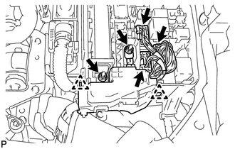
Disconnect the 3 connectors.
-
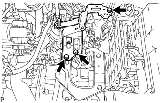
Remove the 2 nuts.
-
Detach the 2 claws and remove the engine room No. 1 relay block.
-
for Automatic Transaxle:
Disconnect the TCM connector.
-
for Manual Transaxle:
Detach the 4 clamps and disconnect the wire harness.
-
for Automatic Transaxle:
Detach the clamp, remove the bolt and disconnect the ground cable.
-
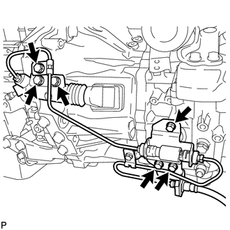
Disconnect the 2 fuel hoses.
-
for Manual Transaxle:
Remove the bolt and disconnect the ground cable.
-
Disconnect the vacuum pump hose.
-
-
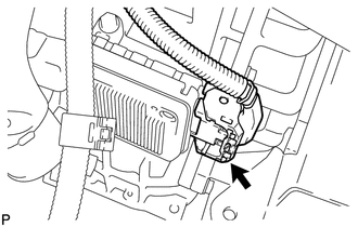
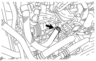
DISCONNECT INLET HEATER WATER HOSE
-
Disconnect the inlet heater water hose.
-
-
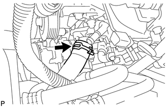
DISCONNECT OUTLET HEATER WATER HOSE
-
Disconnect the outlet heater water hose.
-
-
DISCONNECT NO. 1 RADIATOR HOSE (for Manual Transaxle)
-
Disconnect the No. 1 radiator hose.
-
-
REMOVE INTERCOOLER AIR HOSE (for Manual Transaxle)
-
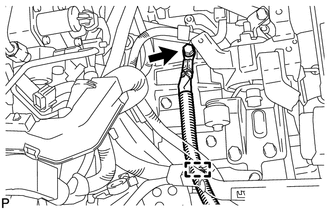
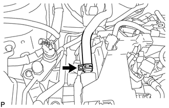
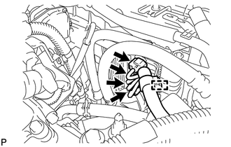
DISCONNECT WATER BY-PASS HOSE
-
Disconnect the water by-pass hose.
-
-
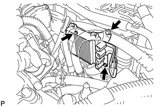
DISCONNECT NO. 2 RADIATOR HOSE (for Manual Transaxle)
-
Disconnect the No. 2 radiator hose.
-
-
REMOVE INJECTOR DRIVER (for Manual Transaxle)
-
Detach the clamp and disconnect the 4 connectors.
-
Remove the 3 screws and injector driver.
-
-
REMOVE FRONT SUSPENSION MEMBER REINFORCEMENT RH
-
REMOVE FAN AND GENERATOR V BELT
-
DISCONNECT COMPRESSOR WITH PULLEY ASSEMBLY (w/ Air Conditioning System)
-
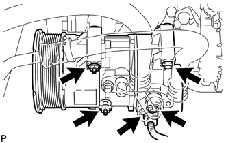
Disconnect the connector.
-
Remove the 2 bolts and 2 nuts.
-
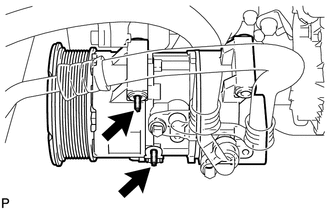
Using an E8 "TORX" socket wrench, remove the 2 stud bolts and disconnect the compressor.
Tech Tips
It is not necessary to completely remove the compressor. With the hoses connected to the compressor, hang the compressor on the vehicle body with a rope.
-
-
DISCONNECT TRANSMISSION CONTROL CABLE ASSEMBLY (for Manual Transaxle)
-
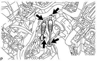
Remove the 2 pins.
-
Remove the 2 clips and disconnect the 2 transmission control cables from the control cable bracket.
-
-
DISCONNECT TRANSMISSION CONTROL CABLE ASSEMBLY (for Automatic Transaxle)
-
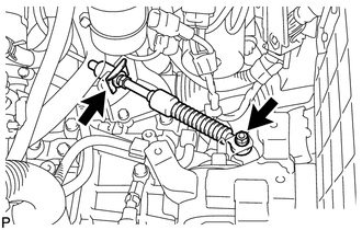
Remove the nut and clip, and disconnect the transmission control cable.
-
-
DISCONNECT CLUTCH RELEASE CYLINDER ASSEMBLY (for Manual Transaxle)
-
Remove the 6 bolts and disconnect the clutch release cylinder and flexible hose bracket.
-
-
SECURE STEERING WHEEL
-
REMOVE COLUMN HOLE COVER SILENCER SHEET
-
DISCONNECT NO. 2 STEERING INTERMEDIATE SHAFT ASSEMBLY
-
REMOVE NO. 1 STEERING COLUMN HOLE COVER SUB-ASSEMBLY
-
REMOVE FRONT AXLE SHAFT NUT LH
-
REMOVE FRONT AXLE SHAFT NUT RH
Tech Tips
Perform the same procedure as for the LH side.
-
DISCONNECT FRONT STABILIZER LINK ASSEMBLY LH
-
DISCONNECT FRONT STABILIZER LINK ASSEMBLY RH
Tech Tips
Perform the same procedure as for the LH side.
-
REMOVE FRONT AXLE ASSEMBLY LH
-
REMOVE FRONT AXLE ASSEMBLY RH
-
REMOVE FRONT DRIVE SHAFT ASSEMBLY LH
-
REMOVE FRONT DRIVE SHAFT ASSEMBLY RH
-
REMOVE FRONT SUSPENSION MEMBER REINFORCEMENT LH
-
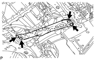
Remove the 4 bolts and front suspension member reinforcement LH.
-
-
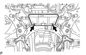
REMOVE FRONT CROSSMEMBER SUB-ASSEMBLY
-
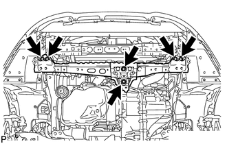
Remove the 6 bolts and front crossmember.
-
-
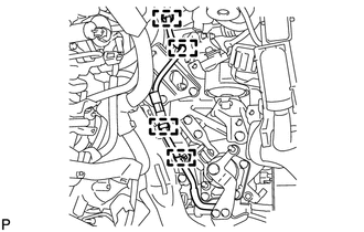
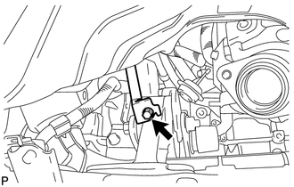
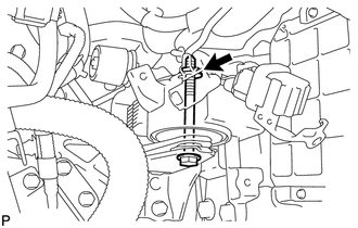
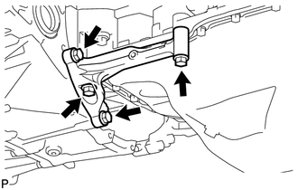
REMOVE FRONT ENGINE MOUNTING INSULATOR
-
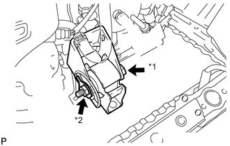
Text in Illustration *1 Through Bolt *2 Nut Remove the through bolt, nut and front engine mounting insulator.
-
-
REMOVE ENGINE WITH TRANSAXLE
-
Remove the bolt and disconnect the cable bracket.
-
Detach the 3 clamps and disconnect the wire harness.
-
Set an engine lifter underneath the engine.
Tech Tips
Place the engine on wooden blocks or equivalent so that the engine is level.
-
Remove the 2 bolts and 2 nuts, and disconnect the engine mounting insulator RH.
-
Remove the bolt and nut and disconnect the engine mounting insulator LH.
-
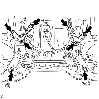
Remove the 6 bolts and front suspension member rear brace RH and LH.
-
Remove the 2 bolts and suspension crossmember.
-
Carefully remove the engine with transaxle from the vehicle.
-
Text in Illustration *1 No. 1 Engine Hanger *2 No. 2 Engine Hanger Install 2 engine hangers with 2 bolts as shown in the illustration.
- Torque:
- 40 N*m { 408 kgf*cm, 30 ft.*lbf }
Tech Tips
Part No. No. 1 engine hanger 12281-26040 No. 2 engine hanger 12282-26010 Bolt 91552-81025 or 90105-W0042
-
Insert the claw of the No. 1 engine hanger into the hole of the cylinder head.
-
Fit the fork part of the No. 2 engine hanger onto the rib of the cylinder head.
-
Attach an engine sling device and hang the engine with a chain block.
-
-
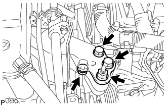
REMOVE REAR ENGINE MOUNTING INSULATOR
-
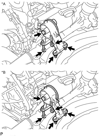
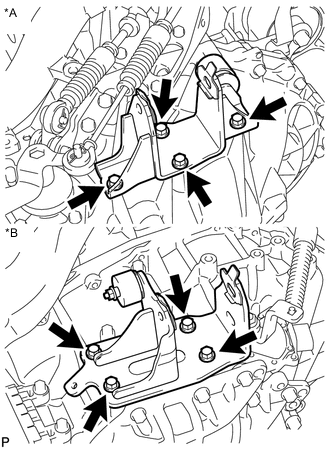
Text in Illustration *A for Manual Transaxle *B for Automatic Transaxle Remove the 3 bolts, 2 nuts and rear engine mounting insulator.
-
-
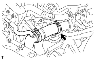
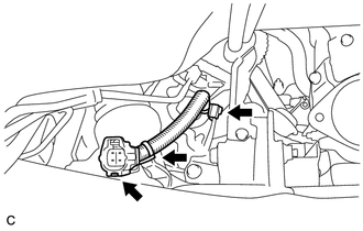
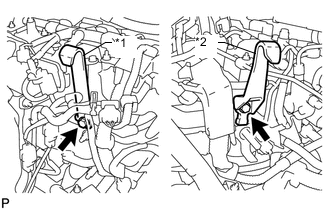
REMOVE NO. 1 AIR TUBE
-
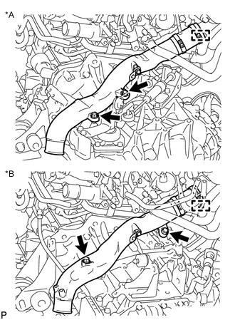
Text in Illustration *A for Manual Transaxle *B for Automatic Transaxle Loosen the hose clamp, and remove the 2 bolts and No. 1 air tube.
-
-
REMOVE STARTER ASSEMBLY (for VALEO Made)
-
REMOVE STARTER ASSEMBLY (for DENSO Made)
-
REMOVE ENGINE WIRE
-
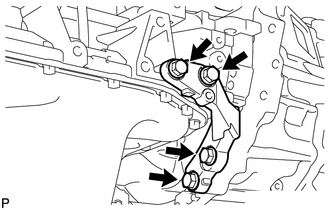
REMOVE FRONT ENGINE MOUNTING BRACKET (for Manual Transaxle)
-
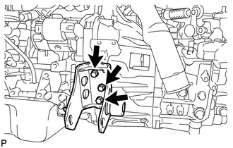
Remove the 3 bolts and front engine mounting bracket.
-
-
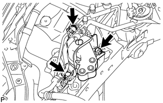
REMOVE FRONT ENGINE MOUNTING BRACKET (for Automatic Transaxle)
-
Remove the 4 bolts and front engine mounting bracket.
-
-
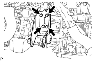
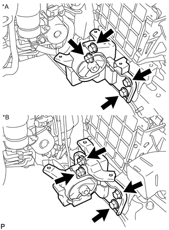
REMOVE REAR ENGINE MOUNTING BRACKET (for Manual Transaxle)
-
Remove the 5 bolts and rear engine mounting bracket.
-
-
REMOVE REAR ENGINE MOUNTING BRACKET (for Automatic Transaxle)
-
Remove the 4 bolts and rear engine mounting bracket.
-
-
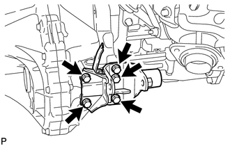
REMOVE ENGINE MOUNTING BRACKET LH
Tech Tips
Perform this procedure only when replacement of the engine mounting bracket is necessary.
-
Text in Illustration *A for Manual Transaxle *B for Automatic Transaxle Remove the 4 bolts and engine mounting bracket LH from the transaxle.
-
-
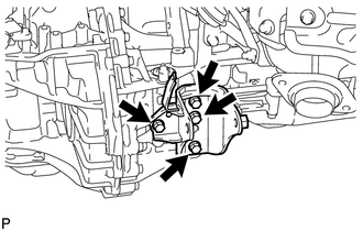
REMOVE ENGINE MOUNTING INSULATOR LH
Tech Tips
Perform this procedure only when replacement of the engine mounting insulator is necessary.
-
Text in Illustration *A for Manual Transaxle *B for Automatic Transaxle Remove the 4 bolts and engine mounting insulator LH from the body.
-
-
REMOVE ENGINE MOUNTING INSULATOR RH
Tech Tips
Perform this procedure only when replacement of the engine mounting insulator is necessary.
-
Remove the 3 bolts and engine mounting insulator RH from the body.
-
-
REMOVE OIL PAN INSULATOR
-
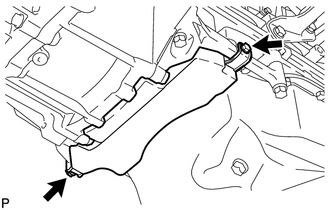
Remove the 2 bolts and oil pan insulator.
-
-
REMOVE STIFFENER PLATE RH
-
Remove the 4 bolts and stiffener plate RH.
-
-
REMOVE STIFFENER PLATE LH
-
Remove the 4 bolts and stiffener plate LH.
-
-
REMOVE MANUAL TRANSAXLE ASSEMBLY (for Manual Transaxle)
-
REMOVE AUTOMATIC TRANSAXLE ASSEMBLY (for Automatic Transaxle)
-
REMOVE CLUTCH COVER ASSEMBLY (for Manual Transaxle)
-
REMOVE CLUTCH DISC ASSEMBLY (for Manual Transaxle)
-
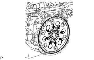
REMOVE FLYWHEEL SUB-ASSEMBLY (for Manual Transaxle)
-
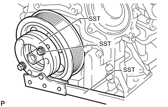
Hold the crankshaft pulley with SST.
- SST
- 09213-58014 ( 91551-80840 )
- 09330-00021
-
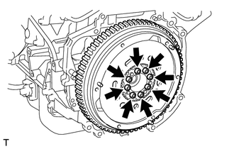
Using a T55 "TORX" socket wrench, remove the 8 bolts and flywheel.
-
-
REMOVE DRIVE PLATE AND RING GEAR SUB-ASSEMBLY (for Automatic Transaxle)
-
Remove the 8 bolts, rear drive plate spacer, drive plate and ring gear, and front drive plate spacer.
-
-
INSTALL ENGINE TO ENGINE STAND
-
Install the engine to an engine stand, and remove the sling device and chain block from the engine.
-
Remove the 2 bolts and No. 1 and No. 2 engine hangers.
-