POWER MANAGEMENT CONTROL ECU INSTALLATION
PROCEDURE
-
INSTALL ECU INTEGRATION BOX ADAPTER (for LHD, except Type A)
-
Install the ECU integration box adapter to the power management control ECU.
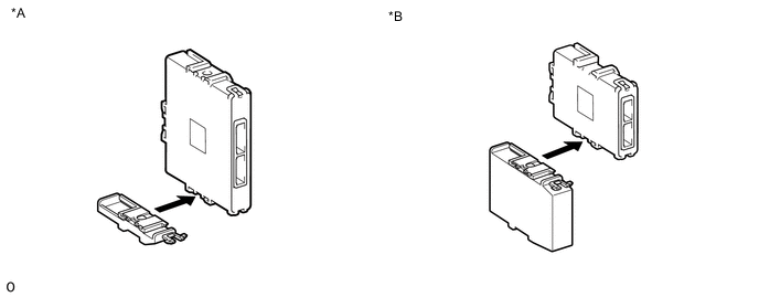
Text in Illustration *A for Type B *B for Type C
-
-
INSTALL POWER MANAGEMENT CONTROL ECU (for LHD)
-
for Type A:
Insert the power management control ECU to the ECU integration box RH.
-
for Type B, for Type C:
Insert the power management control ECU together with the ECU integration box adapter to the ECU integration box RH.
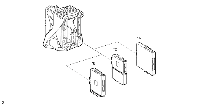
Text in Illustration *A for Type A *B for Type B *C for Type C - - -
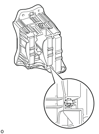
for Type A:
Push in the power management control ECU to attach the 2 claws.
-
for Type B, for Type C:
Push in the power management control ECU together with the ECU integration box adapter to attach the 2 claws.
-
-
INSTALL POWER MANAGEMENT CONTROL ECU (for RHD)
-
for Type A, for Type B:
Install the power management control ECU with the 2 bolts.
- Torque:
- 13 N*m { 127 kgf*cm, 9 ft.*lbf }
-
for Type C:
Install the power management control ECU with the bolt.
- Torque:
- 13 N*m { 127 kgf*cm, 9 ft.*lbf }
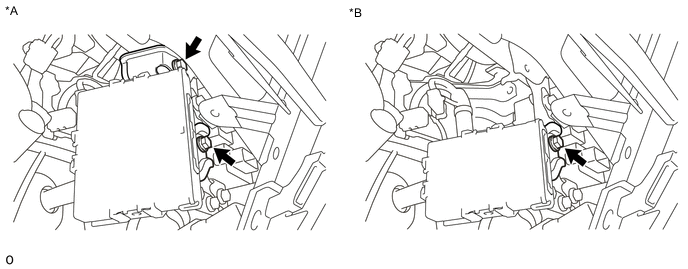
Text in Illustration *A for Type A, for Type B *B for Type C -
Connect the 2 connectors.
-
-
INSTALL ECU INTEGRATION BOX RH (for LHD)
-
INSTALL NO. 2 INSTRUMENT PANEL UNDER COVER SUB-ASSEMBLY (for LHD)
-
INSTALL GLOVE COMPARTMENT DOOR ASSEMBLY (for LHD)
-
INSTALL LOWER NO. 1 INSTRUMENT PANEL AIRBAG ASSEMBLY (for RHD)
-
CONNECT CABLE TO NEGATIVE BATTERY TERMINAL
Note
When disconnecting the cable, some systems need to be initialized after the cable is reconnected Click here.
-
CHECK SRS WARNING LIGHT (for RHD)