AUDIO AND VISUAL SYSTEM(for Radio and Display Type), Diagnostic DTC:B157D
| DTC Code | DTC Name |
|---|---|
| B157D | DAB Tuner Antenna Disconnected |
DESCRIPTION
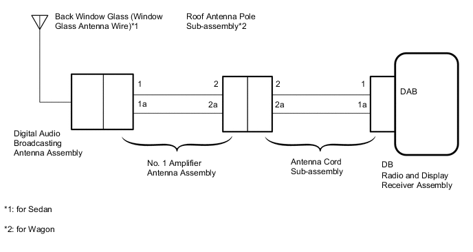
This DTC is stored when a malfunction occurs in the digital audio broadcasting antenna cable which is connected to the radio and display receiver assembly.
| DTC Code | DTC Detection Condition | Trouble Area |
|---|---|---|
| B157D | The digital audio broadcasting cable is not connected. |
|
WIRING DIAGRAM
CAUTION / NOTICE / HINT
Tech Tips
Check that the wire harness is properly installed and does not have any sharp bends, pinching or loose connections Click here.
PROCEDURE
-
CHECK CONNECTION OF DAB RADIO ANTENNA CABLE
-
Check if the DAB radio antenna cable is securely connected to the radio and display receiver assembly.
OK DAB radio antenna cable is securely connected
NG 
SECURELY CONNECT DAB RADIO ANTENNA CABLE
OK 
-
-
CHECK RADIO AND DISPLAY RECEIVER ASSEMBLY
-
Remove the antenna connector from the radio and display receiver assembly.
-
Turn the ignition switch to ACC with the radio and display receiver assembly connector connected.
-
Turn on the radio and turn into AM mode.
-
Place a screwdriver, thin wire or other metal object on the radio and display receiver assembly antenna jack and check that noise can be heard from the speakers.
OK Noise occurs.
NG
REPLACE RADIO AND DISPLAY RECEIVER ASSEMBLY Click here
OK
-
-
CHECK VEHICLE TYPE
-
Check the vehicle type.
Result Result Proceed to for Sedan A for wagon B
B 
CHECK ROOF ANTENNA POLE SUB-ASSEMBLY Click here
A
-
-
CHECK BACK WINDOW GLASS (WINDOW GLASS ANTENNA WIRE)
-
Check the back window glass (window glass antenna wire) Click here.
NG
REPAIR BACK WINDOW GLASS Click here
OK
-
-
CHECK ANTENNA CORD SUB-ASSEMBLY
-
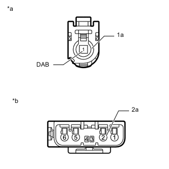
Text in Illustration *a Front view of wire harness connector
(to Radio and Display Receiver Assembly)
*b Front view of wire harness connector
(to No. 1 Amplifier Antenna Assembly)
Remove the antenna connector from the radio and display receiver assembly.
-
Remove the antenna connector from the No. 1 amplifier antenna assembly.
-
Measure the resistance according to the value(s) in the table below.
Standard Resistance Tester Connection Condition Specified Condition 1 (DAB) - 2 Always Below 1 Ω 1a - 2a Always Below 1 Ω 1 (DAB) - Body ground Always 10 kΩ or higher 1a - Body ground Always 10 kΩ or higher
NG
REPLACE ANTENNA CORD SUB-ASSEMBLY
OK
-
-
CHECK NO. 1 AMPLIFIER ANTENNA ASSEMBLY
-
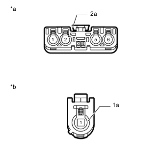
Text in Illustration *a Front view of wire harness connector
(to Antenna Cord Sub-assembly)
*b Front view of wire harness connector
(to Digital Audio Broadcasting Antenna Assembly)
Remove the antenna connector from the antenna cord sub-assembly.
-
Remove the antenna connector from the digital audio broadcasting antenna assembly.
-
Measure the resistance according to the value(s) in the table below.
Standard Resistance Tester Connection Condition Specified Condition 2 - 1 Always Below 1 Ω 2a - 1a Always Below 1 Ω 2 - Body ground Always 10 kΩ or higher 2a - Body ground Always 10 kΩ or higher
NG
REPLACE NO. 1 AMPLIFIER ANTENNA ASSEMBLY Click here
OK
-
-
CHECK DIGITAL AUDIO BROADCASTING ANTENNA ASSEMBLY
-
Replace the digital audio broadcasting antenna assembly with a known good one Click here.
-
Clear the DTCs Click here.
-
Check for DTCs Click here.
OK No DTCs are output.
OK
END (DIGITAL AUDIO BROADCASTING ANTENNA ASSEMBLY IS DEFECTIVE)
NG
REPLACE RADIO AND DISPLAY RECEIVER ASSEMBLY Click here
-
-
CHECK ROOF ANTENNA POLE SUB-ASSEMBLY
-
Check that the roof antenna pole sub-assembly is securely installed.
OK The roof antenna pole sub-assembly is installed properly
NG
REINSTALL ROOF ANTENNA POLE SUB-ASSEMBLY
OK
-
-
CHECK ANTENNA CORD SUB-ASSEMBLY
-
Text in Illustration *a Front view of wire harness connector
(to Radio and Display Receiver Assembly)
*b Front view of wire harness connector
(to No. 1 Amplifier Antenna Assembly)
Remove the antenna connector from the radio and display receiver assembly.
-
Remove the antenna connector from the No. 1 amplifier antenna assembly.
-
Measure the resistance according to the value(s) in the table below.
Standard Resistance Tester Connection Condition Specified Condition 1 (DAB) - 2 Always Below 1 Ω 1a - 2a Always Below 1 Ω 1 (DAB) - Body ground Always 10 kΩ or higher 1a - Body ground Always 10 kΩ or higher
NG
REPLACE ANTENNA CORD SUB-ASSEMBLY
OK
-
-
CHECK NO. 1 AMPLIFIER ANTENNA ASSEMBLY
-
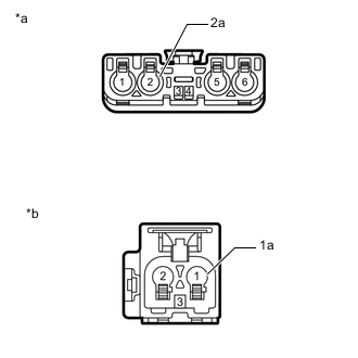
Text in Illustration *a Front view of wire harness connector
(to Antenna Cord Sub-assembly)
*b Front view of wire harness connector
(to Digital Audio Broadcasting Antenna Assembly)
Remove the antenna connector from the antenna cord sub-assembly.
-
Remove the antenna connector from the digital audio broadcasting antenna assembly.
-
Measure the resistance according to the value(s) in the table below.
Standard Resistance Tester Connection Condition Specified Condition 2 - 1 Always Below 1 Ω 2a - 1a Always Below 1 Ω 2 - Body ground Always 10 kΩ or higher 2a - Body ground Always 10 kΩ or higher
NG
REPLACE NO. 1 AMPLIFIER ANTENNA ASSEMBLY Click here
OK
-
-
CHECK DIGITAL AUDIO BROADCASTING ANTENNA ASSEMBLY
-
Replace the digital audio broadcasting antenna assembly with a known good one Click here.
-
Clear the DTCs Click here.
-
Check for DTCs Click here.
OK No DTCs are output.
OK
END (DIGITAL AUDIO BROADCASTING ANTENNA ASSEMBLY IS DEFECTIVE)
NG
-
-
CHECK ROOF ANTENNA POLE SUB-ASSEMBLY
-
Replace the roof antenna pole sub-assembly with a known good one.
-
Clear the DTCs Click here.
-
Check for DTCs Click here.
OK No DTCs are output.
OK
END (ROOF ANTENNA POLE SUB-ASSEMBLY IS DEFECTIVE)
NG
REPLACE RADIO AND DISPLAY RECEIVER ASSEMBLY Click here
-