CAMSHAFT INSTALLATION
PROCEDURE
-
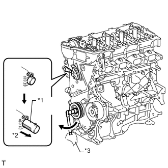
INSTALL VALVE LASH ADJUSTER ASSEMBLY
-
INSTALL NO. 1 VALVE ROCKER ARM SUB-ASSEMBLY
-
INSTALL NO. 2 CAMSHAFT
-
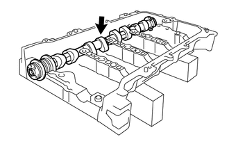
Clean the camshaft journals.
-
Apply a light coat of engine oil to the camshaft journals and camshaft housing.
-
Install the camshaft to the camshaft housing.
-
-
INSTALL CAMSHAFT
-
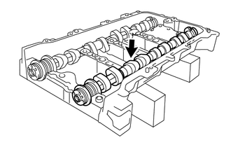
Clean the camshaft journals.
-
Apply a light coat of engine oil to the camshaft journals and camshaft housing.
-
Install the camshaft to the camshaft housing.
-
-
INSTALL CAMSHAFT BEARING CAP
-

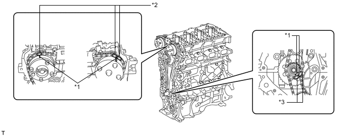
*1 Knock Pin *2 Camshaft Apply engine oil to the camshaft journals, camshaft housing and bearing caps.
-
Check the marks and numbers on the camshaft bearing caps and place the bearing caps in the proper position and direction.
Tech Tips
Make sure that the knock pin of the camshaft is positioned as shown in the illustration.
-
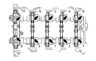
Install the 10 bolts in the order shown in the illustration.
- Torque:
- 16 N*m { 163 kgf*cm, 12 ft.*lbf }
-
-
INSTALL CAMSHAFT HOUSING SUB-ASSEMBLY
-
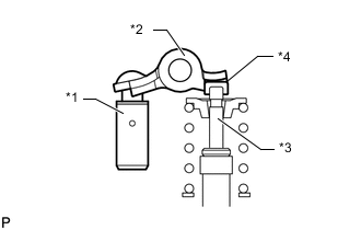
Text in Illustration *1 Lash Adjuster *2 Valve Rocker Arm *3 Valve Stem *4 Valve Stem Cap Make sure that the valve rocker arm is installed as shown in the illustration.
-
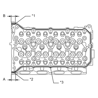
*1 7.0 mm *2 8.0 mm *3 3.5 to 4.5 mm Apply seal packing in a continuous line as shown in the illustration.
Seal packing Toyota Genuine Seal Packing Black, Three Bond 1207B or equivalent Standard Seal Diameter Area Specified Condition Continuous Line 3.5 to 4.5 mm (0.138 to 0.177 in.) A 8.0 mm (0.315 in.) B 7.0 mm (0.276 in.) Application Length A and B 15 mm (0.591 in.) Note
-
Remove any oil from the contact surfaces.
-
Install the camshaft housing within 3 minutes and tighten the bolts within 10 minutes after applying seal packing.
-
Do not start the engine for at least 2 hours after installation.
-
-
Set the camshaft and No. 2 camshaft as shown in the illustration.
-
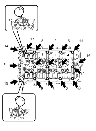
Install the camshaft housing with the 17 bolts and tighten them in the order shown in the illustration.
- Torque:
- 27 N*m { 275 kgf*cm, 20 ft.*lbf }
Note
-
After installing the camshaft housing, make sure that the cam lobes are positioned as shown in the illustration.
-
If any of the bolts are loosened during installation, remove the camshaft housing, clean the installation surfaces, and reapply seal packing.
-
If the camshaft housing is removed because any of the bolts are loosened during installation, make sure that the previously applied seal packing does not enter any oil passages.
-
After installing the camshaft housing, wipe off any seal packing that seeped out from between the housing and cylinder head.
-
-
INSTALL CAMSHAFT TIMING GEAR ASSEMBLY
-
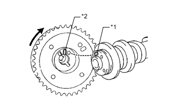
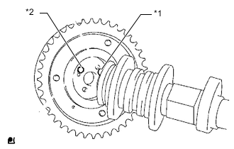
Text in Illustration *1 Straight Pin *2 Key Groove Put the camshaft timing gear and camshaft together with the straight pin and key groove misaligned as shown in the illustration.
Note
Do not forcefully push in the camshaft timing gear. This may cause the camshaft straight pin tip to damage the installation surface of the camshaft timing gear.
-
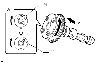
Text in Illustration *1 Straight Pin *2 Key Groove Turn the camshaft timing gear as shown in the illustration while pushing it gently against the camshaft. Push further at the position where the pin fits into the groove.
Note
Do not turn the camshaft timing gear in the retard direction (clockwise).
-

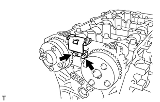
*1 Camshaft Timing Gear *2 Clearance *3 Flange *4 No Clearance Check that there is no clearance between the camshaft timing gear and camshaft flange.
-
Tighten the flange bolt with the camshaft timing gear secured in place.
- Torque:
- 54 N*m { 551 kgf*cm, 40 ft.*lbf }
-

Text in Illustration *1 Lock Check that the camshaft timing gear can move in the retard direction (clockwise) and is locked in the most retarded position.
-
-
INSTALL CAMSHAFT TIMING EXHAUST GEAR ASSEMBLY
-
Text in Illustration *1 Straight Pin *2 Pin Hole Put the camshaft timing exhaust gear and camshaft together by aligning the pin hole and straight pin.
Note
Do not forcefully push in the camshaft timing exhaust gear. This may cause the camshaft straight pin tip to damage the installation surface of the camshaft timing exhaust gear.
-
Lightly press the gear against the camshaft and turn the gear. Push further at the position where the pin enters the hole.
Note
Be sure not to turn the camshaft timing exhaust gear in the retard direction (clockwise).
-
*1 Camshaft Timing Gear *2 Clearance *3 Flange *4 No Clearance Check that there is no clearance between the gear and camshaft flange.
-
Tighten the flange bolt with the camshaft timing exhaust gear secured in place.
- Torque:
- 54 N*m { 551 kgf*cm, 40 ft.*lbf }
-
Check the camshaft timing exhaust gear lock.
-
Make sure that the camshaft timing exhaust gear is locked.
-
-
-
INSTALL NO. 1 CHAIN VIBRATION DAMPER
-
Install the chain vibration damper with the 2 bolts.
- Torque:
- 21 N*m { 214 kgf*cm, 15 ft.*lbf }
-
-
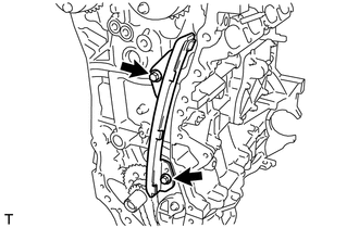
INSTALL NO. 2 CHAIN VIBRATION DAMPER
-
Install the No. 2 chain vibration damper with the 2 bolts.
- Torque:
- 10 N*m { 102 kgf*cm, 7 ft.*lbf }
-
-
SET NO. 1 CYLINDER TO TDC/COMPRESSION
-
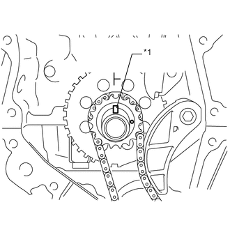
Text in Illustration *1 Timing Gear Key Temporarily install the crankshaft pulley bolt.
-
Turn the crankshaft counterclockwise to position the timing gear key at the top.
-
Text in Illustration *1 Timing Mark Check that the timing marks on the camshaft timing gears are aligned as shown in the illustration.
-
Remove the crankshaft pulley bolt.
-
-
INSTALL CHAIN SUB-ASSEMBLY
-
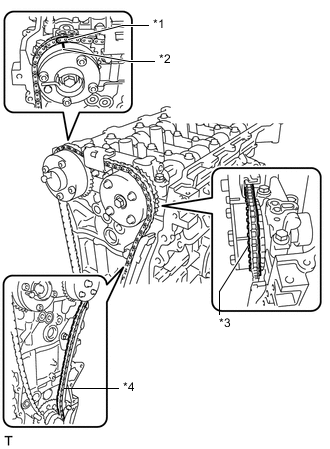
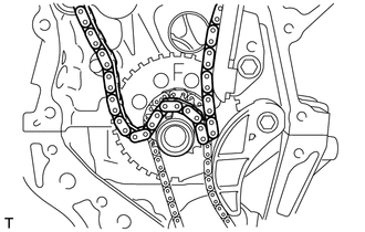
*1 Mark Plate (Orange) *2 Timing Mark *3 Place the Chain on the Sprocket *4 Pass the Chain through the Damper Align the mark plate (orange) with the timing mark as shown in the illustration and install the chain.
Tech Tips
-
Be sure to position the mark plate at the front of the engine.
-
The mark plate on the camshaft side is colored orange.
-
Do not pass the chain around the sprocket of the camshaft timing gear. Only place it on the sprocket.
-
Pass the chain through the No. 1 vibration damper.
-
-
Place the chain on the crankshaft without passing it around the shaft.
-
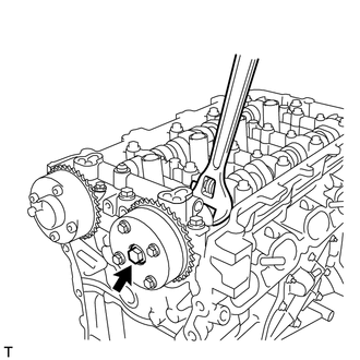
Hold the hexagonal portion of the camshaft with a wrench and turn the camshaft timing gear counterclockwise to align the mark plates (orange) and timing mark, and then install the chain.
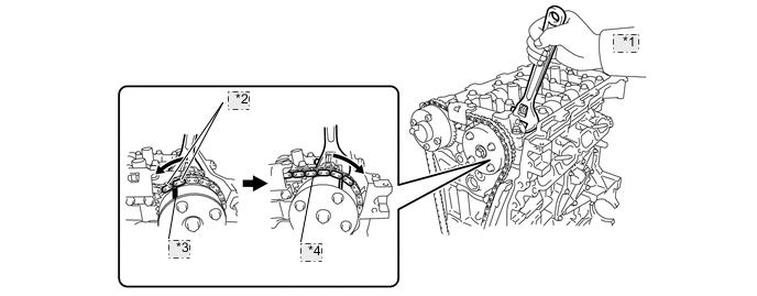
*1 Turn *2 Mark Plate (Orange) *3 Timing Mark *4 Tension the Chain Tech Tips
-
Be sure to position the mark plates at the front of the engine.
-
The mark plates on the camshaft side are colored orange.
-
-
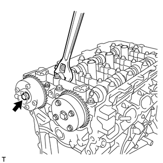
Hold the hexagonal portion of the camshaft with a wrench and turn the camshaft timing gear clockwise.
Tech Tips
To tension the chain, slowly turn the camshaft timing gear clockwise to prevent the chain from being misaligned.
-
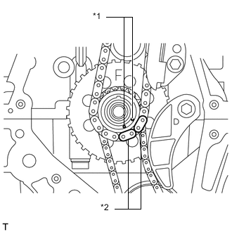
Text in Illustration *1 Timing Mark *2 Mark Plate (Yellow) Align the mark plates (yellow) and timing marks and install the chain to the crankshaft timing gear.
Tech Tips
The mark plates on the crankshaft side are colored yellow.
-
-
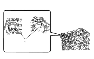
INSTALL CHAIN TENSIONER SLIPPER
-
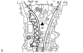
Install the chain tensioner slipper to the cylinder block.
-
-
CHECK NO. 1 CYLINDER TO TDC/COMPRESSION
-
Check each timing mark at TDC/compression.
Text in Illustration *1 Timing Mark *2 Mark Plate (Orange) *3 Mark Plate (Yellow) -
-
-
INSTALL TIMING CHAIN COVER SUB-ASSEMBLY
-
INSTALL TIMING CHAIN COVER OIL SEAL
-
INSTALL CRANKSHAFT PULLEY
-
INSTALL NO. 1 CHAIN TENSIONER ASSEMBLY
-
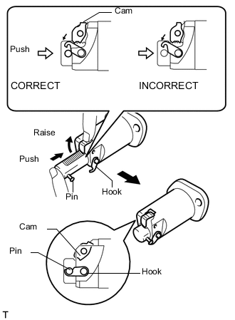
Release the cam, and then fully push in the plunger and engage the hook to the pin so that the plunger is in the position shown in the illustration.
Note
Make sure that the cam engages the first tooth of the plunger to allow the hook to pass over the pin.
-
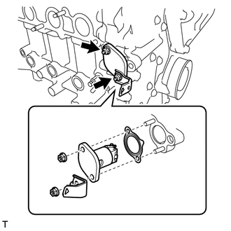
Install a new gasket, the chain tensioner and bracket with the 2 nuts.
- Torque:
- 12 N*m { 122 kgf*cm, 9 ft.*lbf }
Note
If the hook releases the plunger while the chain tensioner is being installed, set the hook again.
-
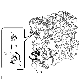
Text in Illustration *1 Release *2 Pin *3 Hook *4 Turn Rotate the crankshaft counterclockwise slightly and check that the hook becomes released.
-
Text in Illustration *1 Plunger *2 Plunger Extended *3 Turn Turn the crankshaft clockwise and check that the plunger is extended.
-
-
INSTALL SPARK PLUG TUBE GASKET
-
INSTALL CYLINDER HEAD COVER GASKET
-
INSTALL CYLINDER HEAD COVER SUB-ASSEMBLY
-
INSTALL RADIO SETTING CONDENSER
-
INSTALL IGNITION COIL ASSEMBLY
-
INSTALL THERMOSTAT
-
INSTALL WATER INLET
-
INSTALL WATER INLET HOSE
-
CONNECT NO. 3 WATER BY-PASS HOSE
-
INSTALL ENGINE OIL LEVEL DIPSTICK GUIDE
-
INSTALL FUEL INJECTOR ASSEMBLY
-
INSTALL NO. 1 DELIVERY PIPE SPACER
-
INSTALL FUEL DELIVERY PIPE SUB-ASSEMBLY
-
INSTALL FUEL TUBE SUB-ASSEMBLY
-
INSTALL AIR TUBE
-
INSTALL INTAKE MANIFOLD
-
INSTALL THROTTLE BODY ASSEMBLY
-
INSTALL ENGINE ASSEMBLY WITH TRANSAXLE
-
Install the engine assembly with transaxle Click here.
-