CAMSHAFT REMOVAL
PROCEDURE
-
REMOVE ENGINE ASSEMBLY WITH TRANSAXLE
-
Remove the engine assembly with transaxle Click here.
-
-
REMOVE THROTTLE BODY ASSEMBLY
-
REMOVE INTAKE MANIFOLD
-
REMOVE AIR TUBE
-
REMOVE FUEL TUBE SUB-ASSEMBLY
-
REMOVE FUEL DELIVERY PIPE SUB-ASSEMBLY
-
REMOVE FUEL INJECTOR ASSEMBLY
-
REMOVE ENGINE OIL LEVEL DIPSTICK GUIDE
-
DISCONNECT NO. 3 WATER BY-PASS HOSE
-
REMOVE WATER INLET HOSE
-
REMOVE WATER INLET
-
REMOVE THERMOSTAT
-
REMOVE IGNITION COIL ASSEMBLY
-
REMOVE RADIO SETTING CONDENSER
-
REMOVE CYLINDER HEAD COVER SUB-ASSEMBLY
-
REMOVE CYLINDER HEAD COVER GASKET
-
REMOVE SPARK PLUG TUBE GASKET
-
SET NO. 1 CYLINDER TO TDC/COMPRESSION
-
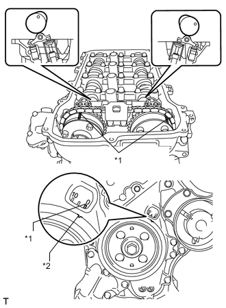
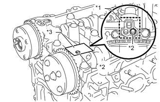
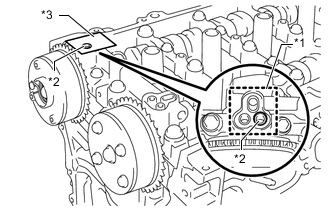
Text in Illustration *1 Timing Mark *2 Timing Notch Turn the crankshaft pulley until its notch and timing mark "0" of the timing chain cover are aligned.
-
Check that timing marks on both the camshaft timing exhaust gear and camshaft timing gear are facing upward as shown in the illustration.
Tech Tips
If not, turn the crankshaft 1 complete revolution (360°) and align the marks as above.
-
-
REMOVE CRANKSHAFT PULLEY
-
REMOVE NO. 1 CHAIN TENSIONER ASSEMBLY
-
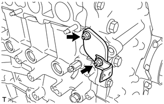
Remove the 2 nuts, bracket, chain tensioner and gasket.
Note
Do not turn the crankshaft without the No. 1 chain tensioner installed.
-
-
REMOVE TIMING CHAIN COVER SUB-ASSEMBLY
-
REMOVE TIMING CHAIN COVER OIL SEAL
-
REMOVE CHAIN TENSIONER SLIPPER
-
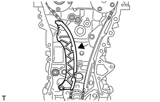
Remove the chain tensioner slipper.
-
-
REMOVE NO. 1 CHAIN VIBRATION DAMPER
-
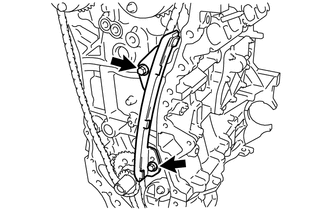
Remove the 2 bolts and chain vibration damper.
-
-
REMOVE CHAIN SUB-ASSEMBLY
-
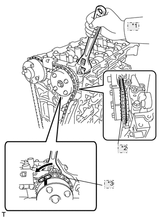
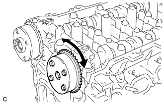
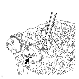
*1 Turn *2 Place the Chain on the Gear *3 Loosen the Chain Hold the hexagonal portion of the camshaft with a wrench and turn the camshaft timing gear counterclockwise to loosen the chain between the camshaft timing gears.
-
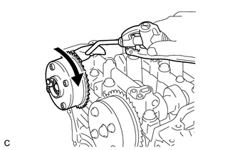
With the chain loosened, release the chain from the camshaft timing gear and place it on the camshaft timing gear.
Tech Tips
Be sure to release the chain from the sprocket completely.
-
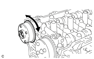
Turn the camshaft clockwise to return it to the original position and remove the chain.
-
-
REMOVE NO. 2 CHAIN VIBRATION DAMPER
-
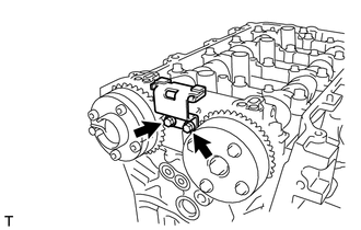
Remove the 2 bolts and chain vibration damper.
-
-
INSPECT CAMSHAFT TIMING GEAR ASSEMBLY
-
Inspect the lock of the camshaft timing gear.
-
After cleaning and degreasing the VVT oil hole on the intake side of the No. 1 camshaft bearing cap, completely seal the oil hole with adhesive tape or equivalent as shown in the illustration to prevent air from leaking.
Text in Illustration *1 Adhesive Tape Sealing Area *2 Prick a Hole *3 Adhesive Tape Note
Be sure to cover the oil hole completely because air leaks due to insufficient sealing will prevent the lock pin from being released.
-
Prick a hole in the tape covering the oil hole as shown in the illustration. (Procedure A)
-
Apply approximately 150 kPa (1.5 kgf/cm2, 22 psi) of air pressure to the hole pricked in procedure A to release the lock pin.
Note
-
If air leaks out, reattach the adhesive tape.
-
Cover the oil hole with a piece of cloth when applying air pressure to prevent oil from spraying.
-
-
Forcibly turn the camshaft timing gear in the advance direction (counterclockwise).
Tech Tips
Depending on the air pressure applied, the camshaft timing gear may turn in the advance direction without assistance.
-
Turn the camshaft timing gear within its movable range (26.5 to 28.5°) 2 or 3 times without turning it to the most retarded position. Make sure that the camshaft timing gear turns smoothly.
-
Remove the adhesive tape from the No. 1 camshaft bearing cap.
-
-
INSPECT CAMSHAFT TIMING EXHAUST GEAR ASSEMBLY
-
Check the lock of the camshaft timing exhaust gear.
-
After cleaning and degreasing the VVT oil hole on the exhaust side of the No. 1 camshaft bearing cap, completely seal the oil hole with adhesive tape or equivalent as shown in the illustration to prevent air from leaking.
Text in Illustration *1 Adhesive Tape Sealing Area *2 Prick a Hole *3 Adhesive Tape Note
Be sure to cover the oil hole completely because air leaks due to insufficient sealing will prevent the lock pin from being released.
-
Prick a hole in the tape covering the oil hole as shown in the illustration. (Procedure A)
-
Apply approximately 200 kPa (2.0 kgf/cm2, 28 psi) of air pressure to the hole pricked in procedure A to release the lock pin.
Note
-
If air leaks out, reattach the adhesive tape.
-
Cover the oil hole with a piece of cloth when applying air pressure to prevent oil from spraying.
-
-
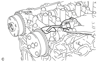
Using a screwdriver with its tip wrapped with tape, forcibly turn the camshaft timing exhaust gear in the retard direction (clockwise).
Note
-
Be sure to keep the camshaft timing exhaust gear in the retard direction using a screwdriver. If the gear is released, it will return to the most advanced position automatically due to the force from the spring.
-
Do not damage the camshaft timing exhaust gear.
-
-
Using a screwdriver with its tip wrapped with tape, turn the camshaft timing exhaust gear within its movable range (19 to 21°) 2 or 3 times without turning it to the most advanced position. Make sure that the camshaft timing exhaust gear turns smoothly.
-
Remove the adhesive tape from the No. 1 camshaft bearing cap.
-
-
REMOVE CAMSHAFT TIMING GEAR ASSEMBLY
-
Remove the flange bolt while holding the hexagonal portion of the camshaft, and then remove the camshaft timing gear.
Note
-
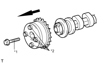
*1 Flange Bolt *2 Do not remove Before removing the camshaft timing gear, make sure that the lock pin has been released.
-
Be sure not to remove the other 4 bolts.
-
Keep the camshaft timing gear horizontal while removing it from the camshaft.
-
-
-
REMOVE CAMSHAFT TIMING EXHAUST GEAR ASSEMBLY
-
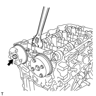
Remove the flange bolt while holding the hexagonal portion of the camshaft, and then remove the camshaft timing exhaust gear.
Note
-
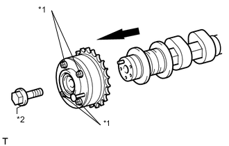
*1 Do not remove *2 Flange Bolt Be sure not to remove the other 4 bolts.
-
Keep the camshaft timing exhaust gear horizontal while removing it from the camshaft.
-
-
-
REMOVE CAMSHAFT BEARING CAP
-
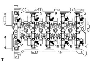
Uniformly loosen and remove the 10 bearing cap bolts in the sequence shown in the illustration.
-
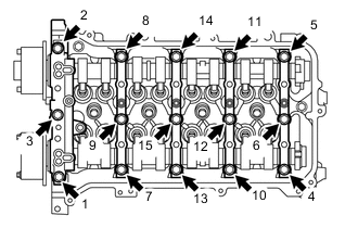
Uniformly loosen and remove the 15 bearing cap bolts in the sequence shown in the illustration.
Note
Uniformly loosen the bolts while keeping the camshaft level.
-
Remove the 5 bearing caps.
Tech Tips
Arrange the removed parts in the correct order.
-
-
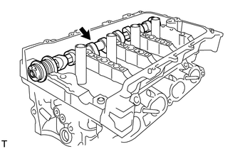
REMOVE CAMSHAFT
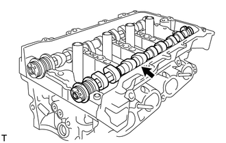
-
REMOVE NO. 2 CAMSHAFT
-
REMOVE NO. 1 VALVE ROCKER ARM SUB-ASSEMBLY
-
REMOVE VALVE LASH ADJUSTER ASSEMBLY
-
REMOVE CAMSHAFT HOUSING SUB-ASSEMBLY
-
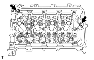
Remove the 2 bolts.
-
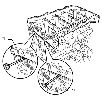
Text in Illustration *1 Protective Tape Remove the camshaft housing by prying between the cylinder head and camshaft housing with a screwdriver.
Tech Tips
Tape the screwdriver tip before use.
Note
Be careful not to damage the contact surfaces of the cylinder head and camshaft housing.
-
-
INSPECT NO. 1 VALVE ROCKER ARM SUB-ASSEMBLY
-
INSPECT VALVE LASH ADJUSTER ASSEMBLY