METER / GAUGE SYSTEM Fuel Economy Meter Malfunction
DESCRIPTION
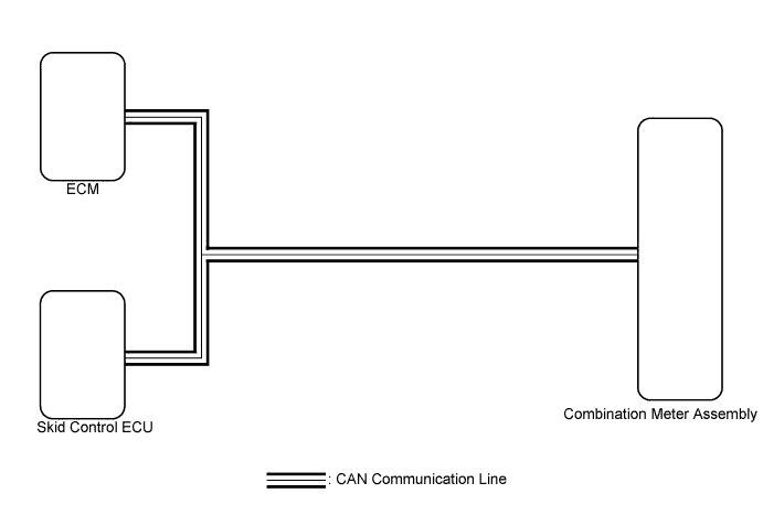
The combination meter communicates with the ECM and skid control ECU via the CAN communication system. The combination meter calculates the current fuel consumption based on a vehicle speed signal from the skid control ECU, a total fuel injection signal from the ECM.
WIRING DIAGRAM
INSPECTION PROCEDURE
PROCEDURE
-
CHECK CAN COMMUNICATION SYSTEM
-
Check if CAN communication DTCs are output Click here.
Result Result Proceed to DTCs are not output. A DTCs are output. B
B 
GO TO CAN COMMUNICATION SYSTEM Click here
A 
-
-
PERFORM ACTIVE TEST USING TECHSTREAM (FUEL CONSUMPTION METER OPERATION)
-
Connect the Techstream to the DLC3.
-
Turn the power switch on (IG).
-
Turn the Techstream on.
-
Enter following menus: Body Electrical / Combination Meter / Active Test.
-
Check the operation by referring to the table below.
Combination Meter Tester Display Test Part Control Range Diagnostic Note Fuel Consumption Meter Operation Fuel consumption meter MIN, 1/4, 1/2, 3/4, MAX - OK Needle indication is normal.
NG
REPLACE COMBINATION METER ASSEMBLY Click here
OK
-
-
READ VALUE USING TECHSTREAM (VEHICLE SPEED, INJECTION VOLUME)
-
Connect the Techstream to the DLC3.
-
Turn the power switch on (IG).
-
Turn the Techstream on.
-
Enter the following menus:
-
for ABS/VSC/TRAC: Chassis / ABS/VSC/TRAC / Data List.
-
for Engine and ECT: Powertrain / Engine and ECT / Data List.
-
-
Check the values by referring to the table below.
ABS/VSC/TRAC Tester Display Measurement Item/Range Normal Condition Diagnostic Note Vehicle Speed Maximum wheel speed sensor reading/Min.: 0 km/h (0 mph), Max.: 326 km/h (202 mph) Vehicle stopped: 0 km/h (0 mph) When driving at constant speed: No large fluctuations Engine and ECT Tester Display Measurement Item/Range Normal Condition Diagnostic Note Injection Volum (Cylinder 1) Injection volume (cylinder 1)/Min.: 0 ml, Max.: 2.047 ml 0 to 0.5 ml
-
Stored as freeze frame data
-
This is the fuel injection volume for 10 injections.
Result Result Proceed to The data list values displayed on the Techstream are within the normal condition. A The data list value displayed on the Techstream differs from the normal condition. (ABS/VSC/TRAC) B The data list value displayed on the Techstream differs from the normal condition. (Engine and ECT) C -
B
GO TO BRAKE CONTROL SYSTEM Click here
C
GO TO SFI SYSTEM (for 2AR-FXE) Click here
A
-
-
REPLACE BRAKE BOOSTER ASSEMBLY
-
Replace the brake booster assembly with a new or a known good one Click here.
Result Result Proceed to The operation of the fuel economy meter returns to normal. A The operation of the fuel economy meter does not return to normal. B
B 
REPLACE ECM Click here
A 
END
-
-
REPLACE ECM
-
Replace the ECM with a new or a known good one Click here.
Result Result Proceed to The operation of the fuel economy meter returns to normal. A The operation of the fuel economy meter does not return to normal. B
B
REPLACE COMBINATION METER ASSEMBLY Click here
A
END
-