BRAKE BOOSTER PUMP INSTALLATION

-
INSTALL BRAKE BOOSTER PUMP ASSEMBLY
-
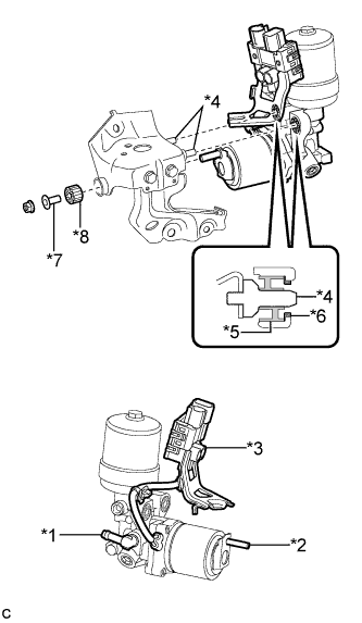
Text in Illustration *1 Union *2 Stud *3 Connector Box and Wire Harness *4 Pin *5 Brake Booster Pump Bushing *6 Brake Booster Pump Collar *7 Brake Actuator Case Collar *8 Brake Booster Pump Bushing Insert the stud of the brake booster pump assembly to the hole of the brake actuator bracket assembly, and insert the 2 pins of the brake actuator bracket assembly to the 2 brake booster pump bushings (*5).
Note
-
Do not carry the brake booster pump assembly by the parts shown in bold (*1, *2 and *3) in the illustration.
-
Do not drop the brake booster pump assembly when carrying it.
-
Be careful not to allow any brake fluid to enter the connector.
-
When installing the brake booster pump assembly to the brake actuator bracket assembly, confirm that the 2 brake booster pump collars (*6) and 2 brake booster pump bushings (*5) are installed on the brake booster pump assembly.
-
Do not remove the hole plugs before installing a new brake booster pump assembly because the brake booster pump assembly is filled with brake fluid.
-
-
Install the brake actuator case collar (*7), brake booster pump bushing (*8) and brake booster pump assembly to the brake actuator bracket assembly with the nut.
- Torque:
- 5.4 N*m { 55 kgf*cm, 48 in.*lbf }
-
Engage the wire harness clamp to the brake actuator bracket assembly.
-
-
INSTALL NO. 1 BRAKE ACTUATOR HOSE
-
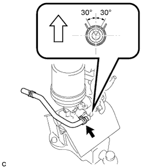
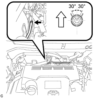
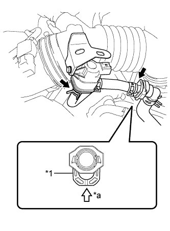
Install the No. 1 brake actuator hose to the brake booster pump assembly with the clip.
Text in Illustration 
Up Note
-
Match the identification mark of the No. 1 brake actuator hose and the rib of the brake booster pump assembly.
-
Install the clip within the range shown in the illustration.
-
-
-
INSTALL BRAKE BOOSTER PUMP ASSEMBLY WITH BRACKET
-
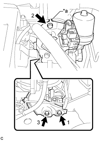
Text in Illustration *a Claw Engage the claw to set the brake booster pump assembly with bracket to the vehicle body.
Note
Do not kink or damage the brake line, suction hose sub-assembly or air conditioning tube and accessory assembly.
-
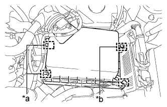
Install the 3 bolts to secure the brake booster pump assembly with bracket to the vehicle body.
- Torque:
- 19 N*m { 194 kgf*cm, 14 ft.*lbf }
Note
Tighten the 3 bolts in the order shown in the illustration.
-
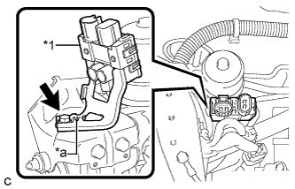
Text in Illustration *1 Connector Box *a Claw Engage the claw to set the connector box to the brake actuator bracket assembly.
-
Install the bolt to secure the connector box to the brake actuator bracket assembly.
- Torque:
- 8.0 N*m { 82 kgf*cm, 71 in.*lbf }
-
Connect the 2 connectors to the brake booster pump assembly.
-
-
CONNECT FRONT NO. 1 BRAKE TUBE
-
Using a union nut wrench, connect the front No. 1 brake tube to the brake booster pump assembly.
- Torque:
- 15 N*m { 155 kgf*cm, 11 ft.*lbf }
Note
Use the formula to calculate special torque values for situations where the union nut wrench is combined with a torque wrench Click here.
-
-
CONNECT NO. 1 BRAKE ACTUATOR HOSE
-
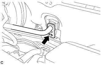
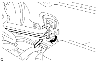
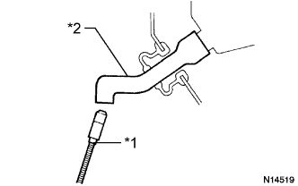
Connect the No. 1 brake actuator hose to the No. 1 brake actuator tube with the clip.
Text in Illustration Up Note
-
Match the identification mark of the No. 1 brake actuator hose and No. 1 brake actuator tube.
-
Install the clip within the range shown in the illustration.
-
-
-
BLEED NO. 1 BRAKE ACTUATOR TUBE
-
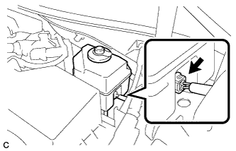
Add brake fluid into the brake master cylinder reservoir assembly.
-
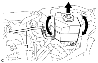
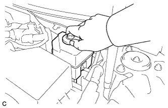
Text in Illustration *1 No. 1 Brake Actuator Tube Lift up the brake master cylinder reservoir assembly as far as possible and rock it back and forth to bleed air from the reservoir tube assembly.
Note
-
Do not damage the hoses or tubes.
-
Do not spill the brake fluid.
-
Continue this procedure until only a minor amount of air remains in the No. 1 brake actuator tube.
-
-
-
INSTALL NO. 1 BRAKE ACTUATOR TUBE
-
Install the No. 1 brake actuator tube to the vehicle body with the nut.
- Torque:
- 8.5 N*m { 87 kgf*cm, 75 in.*lbf }
-
Install the nut and engage the clamp.
- Torque:
- 8.5 N*m { 87 kgf*cm, 75 in.*lbf }
-
-
INSTALL BRAKE MASTER CYLINDER RESERVOIR ASSEMBLY
-
Install the brake master cylinder reservoir assembly to the reservoir bracket with the 2 bolts.
- Torque:
- 8.5 N*m { 87 kgf*cm, 75 in.*lbf }
-
-
INSTALL SUCTION HOSE SUB-ASSEMBLY
-
Remove the vinyl tape from the openings of the disconnected parts.
-
Sufficiently apply compressor oil to a new O-ring, the fitting surface of the suction hose sub-assembly and air conditioning unit.
Compressor oil ND-OIL 11 or equivalent Note
Do not use any compressor oil other than ND-OIL 11 or equivalent. If any compressor oil other than ND-OIL 11 or equivalent is used, compressor motor insulation performance may decrease, resulting in a leakage of electric power.
-
Install the O-ring to the suction hose sub-assembly.
Note
Keep the O-ring and O-ring fitting surfaces free from dirt or any foreign matter.
-
Insert the suction hose sub-assembly to the air conditioning unit.
Note
-
Insert the pipe joint into the fitting hole securely.
-
Do not deform the piping.
-
Do not damage the plastic clamp.
-
-
-
INSTALL AIR CONDITIONER TUBE AND ACCESSORY ASSEMBLY
-
Remove the vinyl tape from the openings of the disconnected parts.
-
Sufficiently apply compressor oil to a new O-ring, the fitting surface of the air conditioning tube and accessory assembly and air conditioning unit.
Compressor oil ND-OIL 11 or equivalent Note
Do not use any compressor oil other than ND-OIL 11 or equivalent. If any compressor oil other than ND-OIL 11 or equivalent is used, compressor motor insulation performance may decrease, resulting in a leakage of electric power.
-
Install the O-ring to the air conditioning tube and accessory assembly.
Note
Keep the O-ring and O-ring fitting surface free from dirt or any foreign matter.
-
Insert the air conditioning tube and accessory assembly to the air conditioning unit.
Note
Insert the pipe joint into the fitting hole securely.
-
Turn the hook connector and install the bolt.
- Torque:
- 9.8 N*m { 100 kgf*cm, 87 in.*lbf }
-
-
FILL RESERVOIR WITH BRAKE FLUID
-
CONNECT CABLE TO AUXILIARY BATTERY NEGATIVE TERMINAL
-
BLEED BRAKE SYSTEM
-
Remove the front outer cowl top panel sub-assembly Click here.
-
Bleed the brake system.
-
Wait at least 2 minutes with the power switch off, and disconnect the reservoir level switch connector.
Note
Do not depress the brake pedal or open/close the doors until the reservoir level switch connector is disconnected.
Tech Tips
This procedure is not required if the reservoir level switch connector has been disconnected.
-
Remove the brake master cylinder reservoir filler cap assembly.
-
Add brake fluid into the reservoir between the MAX and MIN level on the brake fluid reservoir.
Brake fluid SAE J1703 or FMVSS No. 116 DOT3 -
Connect the Techstream to the DLC3 and turn the power switch on (IG).
-
Turn the Techstream on and enter the following menus: Chassis / ABS/VSC/TRAC / Air Bleeding.
-
Select "ABS actuator has been replaced" on the Techstream display, and bleed air from the brake fluid following the instructions on the Techstream.
Note
Before following the instructions on the Techstream to perform linear valve offset calibration, release the parking brake. When calibration is complete, immediately apply the parking brake.
-
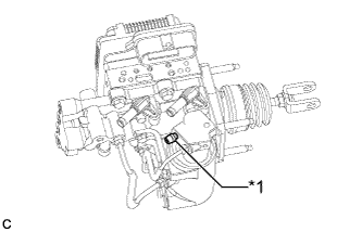
Text in Illustration *1 Stroke Simulator Bleeder Plug After air bleeding, tighten each bleeder plug.
- Torque:
- disc brake cylinder bleeder plug
- 8.3 N*m { 85 kgf*cm, 73 in.*lbf }
- stroke simulator bleeder plug
- 8.5 N*m { 87 kgf*cm, 75 in.*lbf }
Tech Tips
The stroke simulator bleeder plug is positioned as shown in the illustration.
-
Clear the DTCs Click here.
-
Turn the Techstream off and turn the power switch off.
-
-
Install the brake master cylinder reservoir filler cap.
-
Inspect for brake fluid leaks.
-
Install the outer cowl top panel sub-assembly Click here.
-
-
INSTALL AIR CLEANER CASE SUB-ASSEMBLY
-
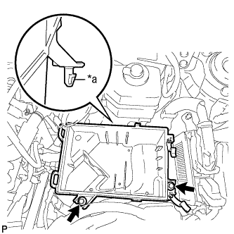
Text in Illustration *a Projection Insert the projection of the air cleaner case sub-assembly into the hole of the No. 2 air cleaner bracket as shown in the illustration.
-
Tighten the 2 bolts.
- Torque:
- 5.0 N*m { 51 kgf*cm, 44 in.*lbf }
-
-
INSTALL AIR CLEANER FILTER ELEMENT SUB-ASSEMBLY
-
INSTALL AIR CLEANER CAP SUB-ASSEMBLY
-
Install the air cleaner hose with the hose clamp.
-
Text in Illustration *1 Retainer *a Push Connect the 2 fuel vapor feed hoses.
Note
-
Check that there are no scratches or foreign matter around the connected part of the fuel tube connector and pipe before performing this work.
-
Connect the quick connector and push the retainer in until the retainer makes a "click" sound to lock the claws of the retainer.
-
After connecting the fuel vapor feed hose to the fuel tube connector, check that the fuel vapor feed hose is securely connected by pulling on the fuel tube connector and the fuel vapor feed hose.
-
-
Text in Illustration *a Hinge *b Clamp Connect the 2 hinges of the air cleaner cap subassembly.
-
Install the air cleaner cap sub-assembly with the 2 clamps.
-
Connect the wire harness clamp and connector.
-
Connect the ventilation hose to the cylinder head cover.
-
Connect the mass air flow meter connector and wire harness clamp to the air cleaner cap sub-assembly.
-
-
INSTALL INLET AIR CLEANER ASSEMBLY
-
Install the inlet air cleaner assembly with the 2 bolts.
- Torque:
- 8.0 N*m { 82 kgf*cm, 71 in.*lbf }
-
-
INSTALL COOL AIR INTAKE DUCT SEAL
-
Install the cool air intake duct seal with the 7 clips.
-
-
CHARGE AIR CONDITIONING SYSTEM WITH REFRIGERANT
-
Perform vacuum purging using a vacuum pump or appropriate equipment.
-
Charge the air conditioning system with refrigerant.
Refrigerant type HFC-134a (R134a) 
Text in Illustration *a Sub-cool System *b High Pressure *c Refrigerant Amount *d Standard charge amount *e Charge additional 100g (3.5oz.) *f Point where bubbles disappear *g Mean value in proper range *h Overcharged Standard charge amount 480 to 580g (16.9 to 20.4oz.) - SST
- 09985-20010 ( 09985-02010, 09985-02050, 09985-02060, 09985-02070, 09985-02080, 09985-02090, 09985-02110, 09985-02130, 09985-02140, 09985-02150 )
Note
-
Do not turn the A/C switch on before charging the air conditioning system with refrigerant. Doing so may cause the compressor to work without refrigerant, resulting in overheating of the compressor.
-
The refrigerant amount should be checked by quantity (weight).
-
The graph above is shown for reference only. This vehicle is not equipped with a sight glass.
Tech Tips
Ensure that sufficient refrigerant is available to recharge the system when using a refrigerant recovery unit. Refrigerant recovery units are not always able to recover 100% of the refrigerant from an air conditioning system.
-
-
WARM UP COMPRESSOR
-
Keep the A/C switch on for at least 2 minutes to warm up the compressor.
Note
To prevent damage to the compressor, be sure to warm up the compressor when turning the air conditioning on after removing and installing air conditioning system lines (including the compressor).
-
-
INSPECT FOR REFRIGERANT LEAK
-
After recharging the air conditioning system with refrigerant, inspect for refrigerant leaks using a halogen leak detector.
-
Carry out the test under the following conditions:
-
Turn the power switch off.
-
Secure good ventilation (the halogen leak detector may react to volatile gases which are not refrigerant, such as gasoline vapor and exhaust gas).
-
Repeat the inspection 2 or 3 times.
-
Measure the pressure to make sure that there is some refrigerant remaining in the air conditioning system.
Pressure when the compressor is off: approx. 392 to 588 kPa (4.0 to 6.0 kgf/cm2, 57 to 85 psi)
-
-
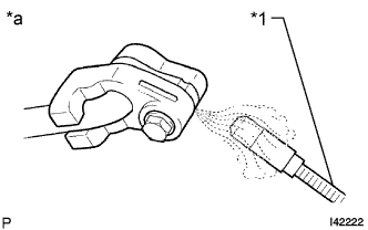
Text in Illustration *1 Halogen Leak Detector *a Inspect for Leak Using a halogen leak detector, inspect for refrigerant leaks from the air conditioning system.
-
Text in Illustration *1 Halogen Leak Detector *2 Drain Hose Bring the halogen leak detector close to the drain hose with the detector power off, and then turn the detector on.
Tech Tips
-
After the blower motor has stopped, leave the cooling unit for more than 15 minutes.
-
Bring the halogen leak detector sensor under the drain hose.
-
When bringing the halogen leak detector close to the drain hose, make sure that the halogen leak detector does not react to volatile gases. If it is not possible to avoid interference from volatile gases, the vehicle should be lifted up to allow checking for leaks.
-
-
If a refrigerant leak is not detected from the drain hose, remove the blower motor control from the cooling unit. Insert the halogen leak detector sensor into the unit and check for a leak.
-
Disconnect the pressure sensor connector and leave it for approximately 20 minutes. Bring the halogen leak detector close to the pressure sensor and check for a leak.
Tech Tips
When checking for leaks, the presence of oily dirt at a joint can indicate a leak.
-
-
INSTALL FRONT OUTER COWL TOP PANEL SUB-ASSEMBLY
-
Install the front outer cowl top panel sub-assembly with the 10 bolts.
- Torque:
- 10 N*m { 102 kgf*cm, 7 ft.*lbf }
-
Engage the 2 clamps to install the wire harness to the front outer cowl top panel sub-assembly.
-
-
INSTALL WINDSHIELD WIPER MOTOR AND LINK ASSEMBLY