SMART ENTRY AND START SYSTEM (for Start Function), Diagnostic DTC:B2283

| DTC Code | DTC Name |
|---|---|
| B2283 | Vehicle Speed Sensor Malfunction |
DESCRIPTION
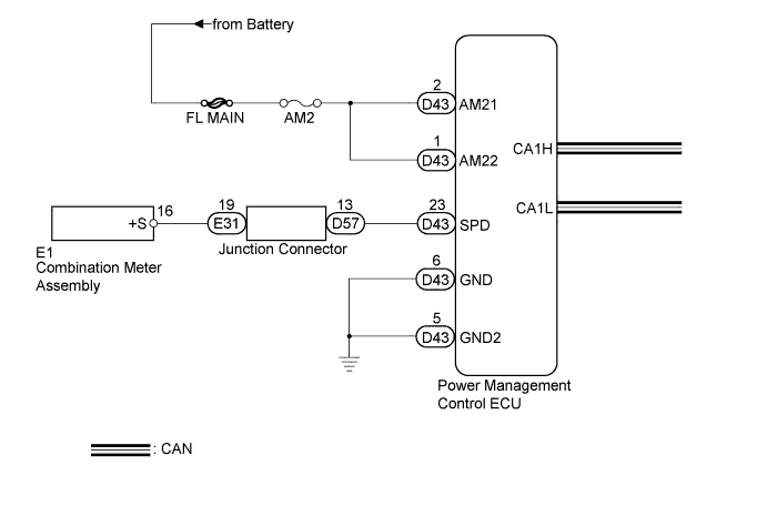
The skid control ECU converts wheel speed sensor signals into 4-pulse signals and sends them to the combination meter. After this signal is converted into a more precise rectangular waveform by the waveform shaping circuit inside the combination meter, it is then transmitted to the power management control ECU. The power management control ECU determines the vehicle speed based on the frequency of these pulse signals.
| DTC No. | DTC Detection Condition | Trouble Area |
|---|---|---|
| B2283 | Both conditions are met:
|
|
WIRING DIAGRAM
INSPECTION PROCEDURE
Note
When the power management control ECU is replaced with a new one and the cable from the negative (-) battery terminal is connected, the power source mode becomes the on (IG) mode. When the battery is removed and reinstalled, the power source mode that was selected when the battery was removed is restored.
PROCEDURE
-
CHECK CAN COMMUNICATION SYSTEM
-
Check if CAN communication DTCs are output.
Tech Tips
If any DTCs for CAN communication system malfunction are output, inspect those DTCs first.
OK CAN communication DTC is not output.
NG 
GO TO CAN COMMUNICATION SYSTEM Click here
OK 
-
-
CHECK SPEEDOMETER OPERATION
-
Connect the GTS to the DLC3.
-
Turn the engine switch on (IG).
-
Turn the GTS on.
-
Enter the following menus: Body Electrical / Combination Meter / Data List.
-
Check the Data List for proper functioning of the vehicle speed signal.
Combination Meter Tester Display Measurement Item/Range Normal Condition Diagnostic Note Vehicle Speed Meter Vehicle speed/Min.: 0, Max.: 255 Almost same as actual speed (When driving) - OK Vehicle speed displayed on the GTS is almost the same as the actual vehicle speed measured using a speedometer tester (calibrated chassis dynamometer).
NG
GO TO METER / GAUGE SYSTEM (Speedometer Malfunction) Click here
OK
-
-
CHECK HARNESS AND CONNECTOR (BATTERY - POWER MANAGEMENT CONTROL ECU)
-
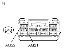
Text in Illustration *1 Front view of wire harness connector
(to Power Management Control ECU)
Disconnect the D43 connector from the power management control ECU.
-
Measure the voltage according to the value(s) in the table below.
Standard Voltage Tester Connection Condition Specified Condition D43-1 (AM22) - Body ground Always 9.5 to 16 V D43-2 (AM21) - Body ground Always 9.5 to 16 V
NG
REPAIR OR REPLACE HARNESS OR CONNECTOR (BATTERY - POWER MANAGEMENT CONTROL ECU)
OK
-
-
CHECK HARNESS AND CONNECTOR (POWER MANAGEMENT CONTROL ECU - BODY GROUND)
-
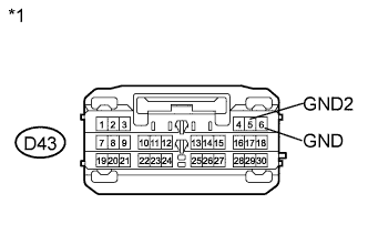
Text in Illustration *1 Front view of wire harness connector
(to Power Management Control ECU)
Disconnect the D43 connector from the power management control ECU.
-
Measure the resistance according to the value(s) in the table below.
Standard Resistance Tester Connection Condition Specified Condition D43-5 (GND2) - Body ground Always Below 1 Ω D43-6 (GND) - Body ground Always Below 1 Ω
NG
REPAIR OR REPLACE HARNESS OR CONNECTOR (POWER MANAGEMENT CONTROL ECU - BODY GROUND)
OK
-
-
CHECK HARNESS AND CONNECTOR (COMBINATION METER - POWER MANAGEMENT CONTROL ECU)
-
Disconnect the E1 connector from the combination meter assembly.
-
Measure the resistance according to the value(s) in the table below.
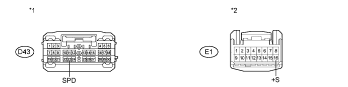
Standard Resistance Tester Connection Condition Specified Condition D43-23 (SPD) - E1-16 (+S) Always Below 1 Ω D43-23 (SPD) - Body ground Always 10 kΩ or higher Text in Illustration *1 Front view of wire harness connector
(to Power Management Control ECU)
*2 Front view of wire harness connector
(to Combination Meter Assembly)
NG 
OK
-
-
READ VALUE USING GTS (VEHICLE SPEED SIGNAL)
-
Connect the GTS to the DLC3.
-
Turn the engine switch on (IG).
-
Turn the GTS on.
-
Enter the following menus: Body Electrical / Power Source Control / Data List.
-
Read the Data List according to the display on the GTS.
Power Source Control Tester Display Measurement Item/Range Normal Condition Diagnostic Note Vehicle Speed Signal Vehicle speed signal/Stop or Run Stop: Vehicle stopped
Run: Vehicle running
- OK Stop (vehicle is stopped) and Run (vehicle is running) appear on the screen.
NG
GO TO METER / GAUGE SYSTEM (Speedometer Malfunction) Click here
OK
-
-
CHECK SPEED SIGNAL INPUT STATUS
-
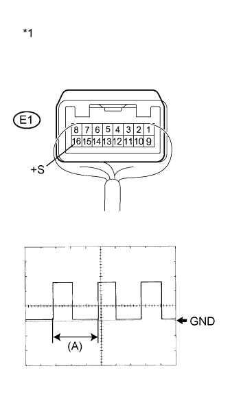
Text in Illustration *1 Component with harness connected
(Combination Meter Assembly)
Remove the combination meter Click here.
-
Reconnect the E1 connector to the combination meter assembly.
-
Reconnect the D43 connector to the power management control ECU.
-
Connect an oscilloscope to terminal E1-16 (+S) and body ground.
-
Turn the engine switch on (IG).
-
Turn the wheel slowly.
-
Check the signal waveform according to the condition(s) in the table below.
Item Condition Tool setting 5 V/DIV., 20 ms./DIV. Vehicle condition Driving at approx. 20 km/h (12 mph) OK The waveform is displayed as shown in the illustration. Tech Tips
When the system is functioning normally, one wheel revolution generates 4 pulses. As the vehicle speed increases, the width indicated by (A) in the illustration narrows.
NG
GO TO METER / GAUGE SYSTEM (Speed Signal Circuit) Click here
OK 
REPLACE POWER MANAGEMENT CONTROL ECU Click here
-
-
CHECK HARNESS AND CONNECTOR (COMBINATION METER ASSEMBLY - JUNCTION CONNECTOR)
-
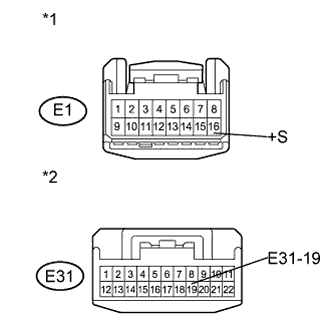
Text in Illustration *1 Front view of wire harness connector
(to Combination Meter Assembly)
*2 Front view of wire harness connector
(to Junction Connector)
Disconnect the E31 connector from the junction connector.
-
Measure the resistance according to the value(s) in the table below.
Standard Resistance Tester Connection Condition Specified Condition E1-16 (+S) - E31-19 Always Below 1 Ω E1-16 (+S) - Body ground Always 10 kΩ or higher
NG
REPAIR OR REPLACE HARNESS OR CONNECTOR (COMBINATION METER - JUNCTION CONNECTOR)
OK
-
-
CHECK HARNESS AND CONNECTOR (JUNCTION CONNECTOR - POWER MANAGEMENT CONTROL ECU)
-
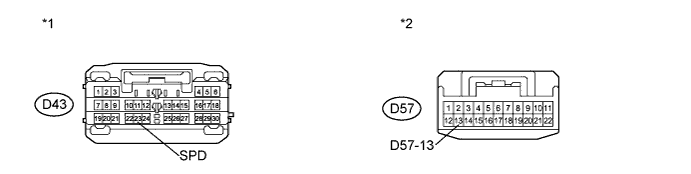
Disconnect the D57 connector from the junction connector.
-
Measure the resistance according to the value(s) in the table below.
Standard Resistance Tester Connection Condition Specified Condition D43-23 (SPD) - D57-13 Always Below 1 Ω D43-23 (SPD) - Body ground Always 10 kΩ or higher Text in Illustration *1 Front view of wire harness connector
(to Power Management Control ECU)
*2 Front view of wire harness connector
(to Junction Connector)
NG
REPAIR OR REPLACE HARNESS OR CONNECTOR (JUNCTION CONNECTOR - POWER MANAGEMENT CONTROL ECU)
OK
REPLACE JUNCTION CONNECTOR
-