МАСЛЯНЫЙ НАСОС УСТАНОВКА

-
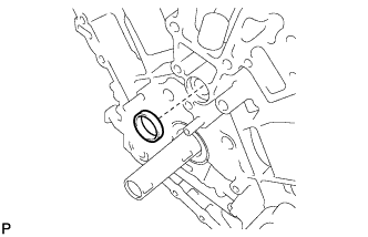
INSTALL WATER INLET PIPE
-
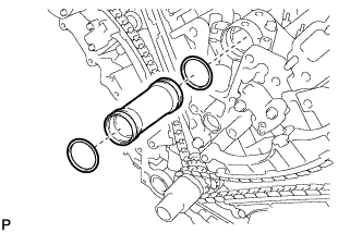
Apply soapy water to 2 new O-rings and install them to the inlet pipe.
-
Install the inlet pipe to the No. 1 heat exchanger cover.
-
-
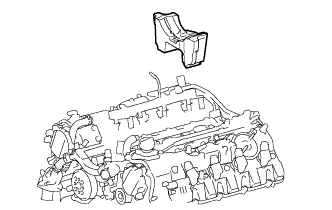
INSTALL TIMING CHAIN COVER SUB-ASSEMBLY
-
Install a new oil pump gasket.
-
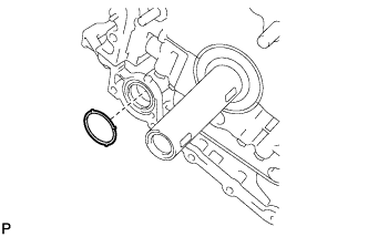
Install a new O-ring.
-
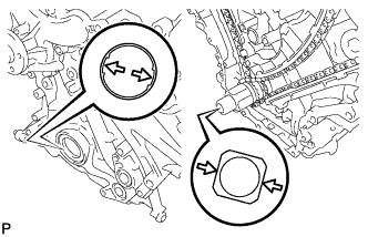
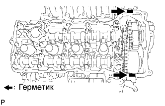
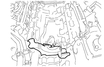
Apply seal packing in a continuous line to the timing chain cover as shown in the following illustration.
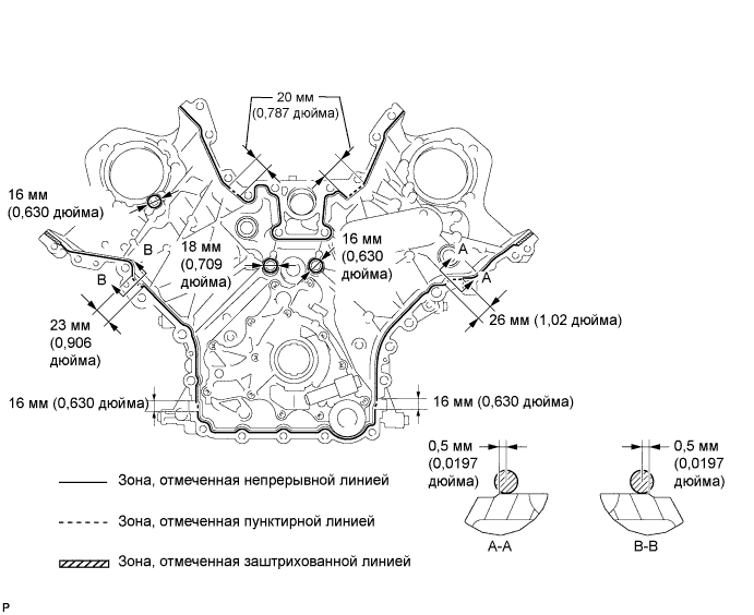
Seal packing Toyota Genuine Seal Packing Black, Three Bond 1207B or equivalent
-
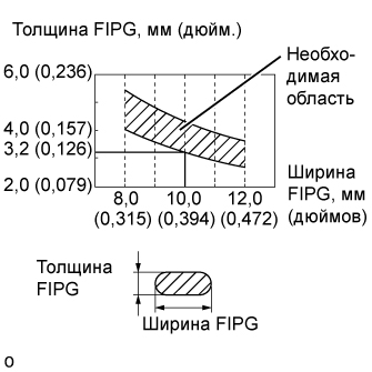
Apply Seal Packing as Follows Area Seal packing diameter Application position from inside edge of cover Continuous Line Area 3.0 to 4.0 mm (0.1181 to 0.1575 in.) 2.5 mm (0.098 in.) Dashed Line Area 6.4 mm (0.2520 in.) or more, or within OK area shown in illustration 0.5 mm (0.020 in.) Diagonal Line Area 3.0 to 4.0 mm (0.1181 to 0.1575 in.) 5.5 mm (0.217 in.)
Note
-
When the contact surfaces are wet, wipe them with an oil-free cloth before applying seal packing.
-
Install the chain cover within 3 minutes and tighten the bolts within 10 minutes after applying seal packing.
-
Do not start the engine for at least 2 hours after installation.
-
-
Align the drive rotor spline of the oil pump and the crankshaft as shown in the illustration. Install the spline and chain cover to the crankshaft.
-
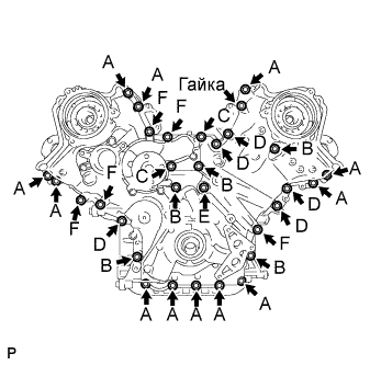
Temporarily tighten the timing chain cover with the 30 bolts and nut.
Bolt Length Item Length Thread diameter Bolt A 25 mm (0.984 in.) 8 mm (0.315 in.) Bolt B 55 mm (2.165 in.) 8 mm (0.315 in.) Bolt C 70 mm (2.756 in.) 8 mm (0.315 in.) Bolt D 35 mm (1.378 in.) 10 mm (0.394 in.) Bolt E 55 mm (2.165 in.) 10 mm (0.394 in.) Bolt F 80 mm (3.150 in.) 10 mm (0.394 in.) Note
Make sure that there is no oil on the bolt threads.
-
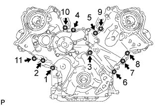
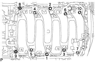
Tighten the 11 bolts in several steps, in the sequence shown in the illustration.
- Torque:
- 47 N*m { 479 kgf*cm, 35 ft.*lbf }
-
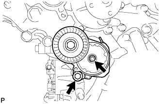
Temporarily tighten the belt tensioner with the standard bolt and 6 mm hexagon wrench bolt.
-
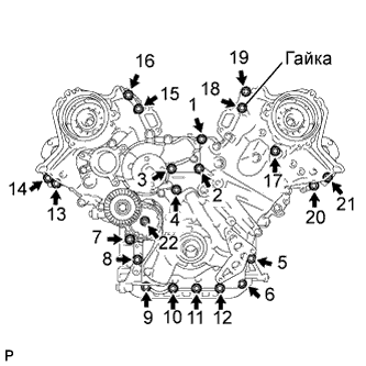
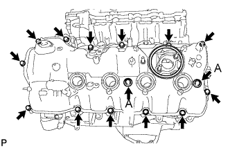
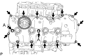
Tighten the 21 bolts and nut in several steps, in the sequence shown in the illustration.
- Torque:
- 23 N*m { 235 kgf*cm, 17 ft.*lbf }
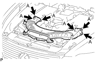
Note
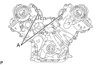
After the installation, if the seal packing has seeped out at the areas labeled A shown in the illustration, wipe it off.
-
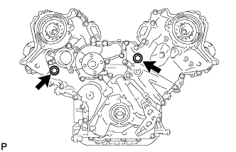
Install the 2 new gaskets and the 2 plugs.
- Torque:
- 46 N*m { 469 kgf*cm, 34 ft.*lbf }
-
-
INSTALL CYLINDER HEAD COVER SUB-ASSEMBLY (for Bank 1)
-
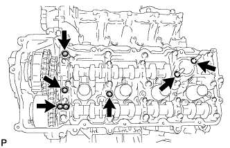
Install 4 new gaskets and 2 new O-rings to the camshaft bearing caps (No. 2, No. 3, No. 7).
-
Install a new gasket to the cylinder head cover.
Note
Remove any oil from the contact surface.
-
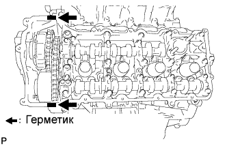
Apply seal packing as shown in the illustration.
Seal packing Toyota Genuine Seal Packing Black, Three Bond 1207B or equivalent Note
-
Remove any oil from the contact surface.
-
Install the cylinder head cover within 3 minutes and tighten the bolts within 15 minutes after applying seal packing.
-
Do not start the engine for at least 2 hours after the installation.
-
-
Install the cylinder head cover with 2 new seal washers and the 15 bolts.
- Torque:
- for bolt A
- 21 N*m { 214 kgf*cm, 15 ft.*lbf }
- except bolt A
- 12 N*m { 122 kgf*cm, 9 ft.*lbf }
-
-
INSTALL CYLINDER HEAD COVER SUB-ASSEMBLY (for Bank 2)
-
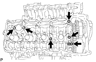
Install 4 new gaskets and 2 new O-rings to the camshaft bearing caps (No. 1, No. 3, No. 6).
-
Install a new gasket to the cylinder head cover.
Note
Remove any oil from the contact surface.
-
Apply seal packing as shown in the illustration.
Seal packing Toyota Genuine Seal Packing Black, Three Bond 1207B or equivalent Note
-
Remove any oil from the contact surface.
-
Install the cylinder head cover within 3 minutes and tighten the bolts within 15 minutes after applying seal packing.
-
Do not start the engine for at least 2 hours after the installation.
-
-
Install the cylinder head cover with 2 new seal washers and the 15 bolts.
- Torque:
- for bolt A
- 21 N*m { 214 kgf*cm, 15 ft.*lbf }
- except bolt A
- 12 N*m { 122 kgf*cm, 9 ft.*lbf }
-
-
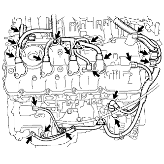
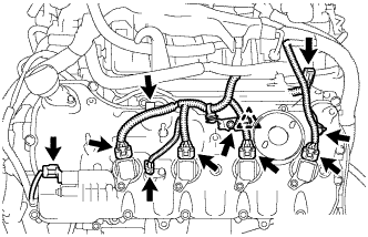
INSTALL IGNITION COIL ASSEMBLY
-
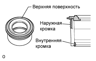
Выполните визуальный осмотр прокладки трубки свечного колодца.
Номинальное значение / Номинальный режим Участок, на котором имеется неисправность Результат проверки Верхняя поверхность Отсутствуют царапины или деформации Наружная кромка Отсутствуют царапины или деформации Внутренняя кромка Отсутствуют царапины -
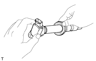
Установите прокладку трубки свечного колодца на каждую катушку зажигания.
-
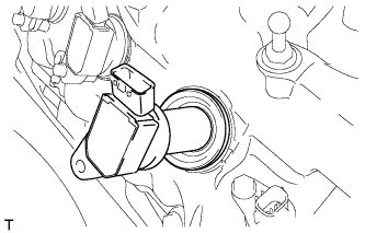
После установки всех прокладок трубок свечных колодцев надежно вставь все катушки зажигания.
-
Вверните 8 болтов.
- Torque:
- 10 Н*м { 102 кгс*см, 7 фунт-сила-футов }
-
Подсоедините 8 разъемов катушек зажигания.
-
-
INSTALL CRANKSHAFT PULLEY
-
Align the pulley set key with the key groove of the pulley, and slide on the pulley.
-
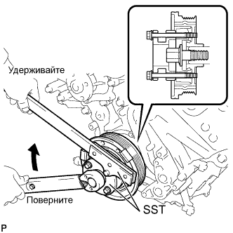
Using SST, install the pulley bolt.
- SST
- 09213-54015 ( 90119-08216 )
- 09330-00021
- Torque:
- 300 N*m { 3059 kgf*cm, 221 ft.*lbf }
-
-
INSTALL RESONATOR BRACKET SUB-ASSEMBLY
-
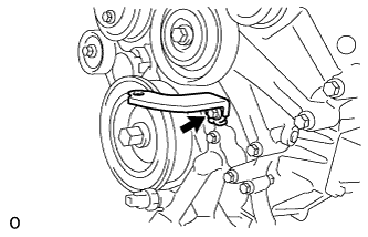
Install the resonator bracket sub-assembly with the bolt.
- Torque:
- 20 N*m { 204 kgf*cm, 15 ft.*lbf }
-
-
INSTALL OIL FILTER BRACKET
-
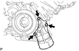
Install 2 new gaskets and the filter bracket with the 3 bolts.
- Torque:
- 21 N*m { 214 kgf*cm, 15 ft.*lbf }
-
-
INSTALL OIL FILTER ELEMENT
-
Clean the inside of the oil filter cap, the threads and O-ring groove.
-
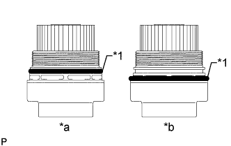
Text in Illustration *1 O-Ring *a CORRECT *b INCORRECT Apply a small amount of engine oil to a new O-ring for the cap, and then install the O-ring to the groove of the oil filter cap.
Note
-
Be sure to install the O-ring in the proper location, otherwise oil may leak.
-
Do not twist the O-ring.
-
-
Set a new oil filter element to the oil filter cap.
-
Remove any dirt or foreign matter from the installation surface of the engine.
-
Apply a small amount of engine oil to the O-ring again and temporarily install the oil filter cap.
Note
Do not pinch the O-ring for the cap.
-
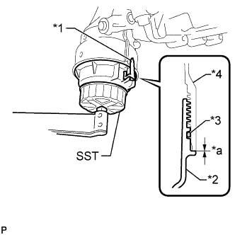
Text in Illustration *1 Oil Filter Bracket *2 Oil Filter Cap *3 O-Ring *4 Oil Filter Bracket *a No Clearance Using SST, tighten the oil filter cap.
- SST
- 09228-06501
- Torque:
- 25 N*m { 255 kgf*cm, 18 ft.*lbf }
Note
-
When tightening the oil filter cap, do not remove the oil filter bracket clip.
-
Make sure that the oil filter is installed securely as shown in the illustration.
-
Be careful that the O-ring does not get caught between the parts.
-
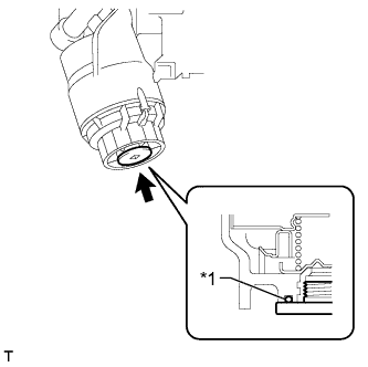
Text in Illustration *1 O-Ring Apply a small amount of engine oil to a new drain plug O-ring, and install it to the oil filter cap.
Note
Before installing the O-ring, remove any dirt or foreign matter from the installation surface of the oil filter cap.
-
Install the oil filter drain plug.
- Torque:
- 13 N*m { 133 kgf*cm, 10 ft.*lbf }
Note
Be careful that the O-ring does not get caught between the parts.
-
-
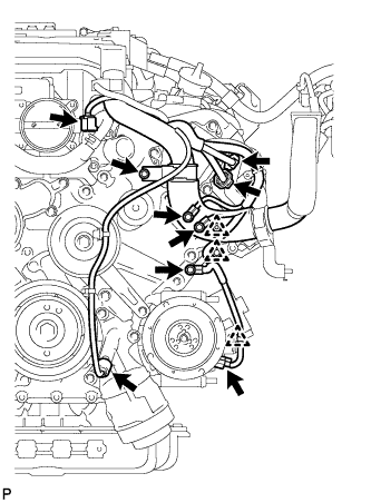
INSTALL CAMSHAFT TIMING CONTROL MOTOR ASSEMBLY LH (for Bank 1)
-
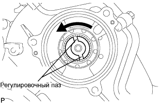
Turn the camshaft timing gear assembly's eccentric shaft index slot in the counterclockwise direction by hand, and set it to the maximum retard angle position.
Tech Tips
-
When the cam of the camshaft lifts the valve, the eccentric shaft becomes difficult to turn.
-
The position where the eccentric shaft stops is the maximum retard angle.
-
-
Install a new O-ring to the timing chain cover.
-
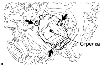
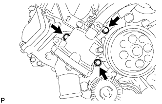
Align the joint of the camshaft timing control motor LH and the keyway of the camshaft timing gear assembly, and install the motor with the 3 bolts.
- Torque:
- 21 N*m { 214 kgf*cm, 15 ft.*lbf }
Note
-
Check that [L] is printed on the label of the camshaft timing control motor LH.
-
Do not allow foreign matter to contact the oil seal face of the camshaft timing control motor LH (connecting surface with timing chain cover sub-assembly).
-
When installing the camshaft timing control motor LH, do not use excessive force.
-
Align the timing chain cover sub-assembly knock pin with the camshaft timing control motor LH pin hole to install the camshaft timing control motor LH.
-
Install the camshaft timing control motor LH with the arrow facing upward, as shown in the illustration.
-
Do not drop the camshaft timing control motor LH. If dropped, replace it.
-
Do not disassemble the camshaft timing control motor LH. If disassembled, replace it.
-
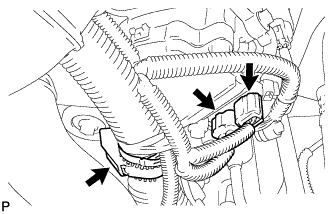
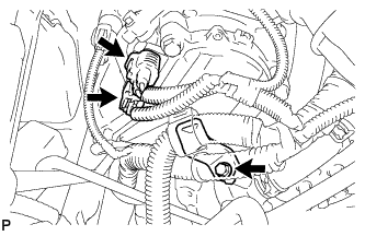
Connect the 2 camshaft timing control motor LH connectors and engine wire clamp.
-
-
INSTALL CAMSHAFT TIMING CONTROL MOTOR ASSEMBLY (for Bank 2)
-
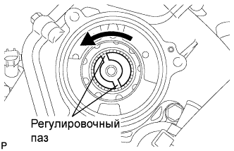
Turn the camshaft timing gear assembly's eccentric shaft index slot in the counterclockwise direction by hand, and set it to the maximum retard angle position.
Tech Tips
-
When the cam of the camshaft lifts the valve, the eccentric shaft becomes difficult to turn.
-
The position where the eccentric shaft stops is the maximum retard angle.
-
-
Install a new O-ring to the timing chain cover.
-
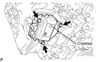
Align the joint of the camshaft timing control motor RH and the keyway of the camshaft timing gear assembly, and install the motor with the 3 bolts.
- Torque:
- 21 N*m { 214 kgf*cm, 15 ft.*lbf }
Note
-
Check that [R] is printed on the label of the camshaft timing control motor RH.
-
Do not allow foreign matter to contact the oil seal face of the camshaft timing control motor RH (connecting surface with timing chain cover sub-assembly).
-
When installing the camshaft timing control motor RH, do not use excessive force.
-
Align the timing chain cover sub-assembly knock pin with the camshaft timing control motor RH pin hole to install the camshaft timing control motor RH.
-
Install the camshaft timing control motor RH with the arrow facing upward, as shown in the illustration.
-
Do not drop the camshaft timing control motor RH. If dropped, replace it.
-
Do not disassemble the camshaft timing control motor RH. If disassembled, replace it.
-
Install the engine wire bracket with the bolt.
- Torque:
- 10 N*m { 102 kgf*cm, 7 ft.*lbf }
-
Connect the 2 camshaft timing control motor RH connectors.
-
-
INSTALL FRONT WATER BY-PASS JOINT
-
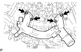
Install the water by-pass joint and 2 new gaskets with the 4 nuts.
- Torque:
- 21 N*m { 214 kgf*cm, 15 ft.*lbf }
-
-
INSTALL NO. 1 IDLER PULLEY SUB-ASSEMBLY
-
Install the bolt and No. 1 idler pulley sub-assembly.
- Torque:
- 43 N*m { 438 kgf*cm, 32 ft.*lbf }
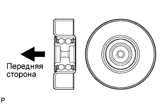
Tech Tips
Install the No. 1 idler pulley sub-assembly in the direction shown in the illustration.
-
-
INSTALL NO. 2 IDLER PULLEY SUB-ASSEMBLY
-
Install the bolt and No. 2 idler pulley sub-assembly.
- Torque:
- 43 N*m { 438 kgf*cm, 32 ft.*lbf }
-
-
INSTALL WATER PUMP PULLEY
-
Temporarily install the pulley with the 4 bolts.
-
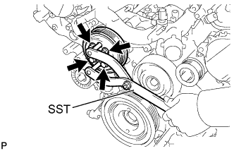
Using SST, hold the pulley and tighten the 4 bolts.
- SST
- 09960-10010 ( 09962-01000, 09963-01000 )
- Torque:
- 21 N*m { 214 kgf*cm, 15 ft.*lbf }
-
-
INSTALL WATER INLET HOUSING
-
Install the inlet housing and new gasket with the 3 bolts.
- Torque:
- 21 N*m { 214 kgf*cm, 15 ft.*lbf }
-
Using needle-nose pliers, grip the claws of the clips and slide the clips to connect the water by-pass hoses and water inlet hose.
-
-
INSTALL NO. 2 ENGINE COVER SUB-ASSEMBLY LH
-
INSTALL NO. 3 ENGINE COVER
-
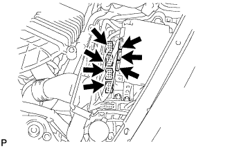
INSTALL INTAKE MANIFOLD
-
Install 2 new gaskets to the intake manifold.
-
Temporarily install the intake manifold with the 2 nuts and 8 bolts. Then tighten the 2 nuts and 8 bolts uniformly in the order shown in the illustration.
- Torque:
- 21 N*m { 214 kgf*cm, 15 ft.*lbf }
-
Connect the No.1 ventilation hose to the intake manifold.
Note
Face the claws of the clips as shown in the illustration.
-
-
INSTALL WATER BY-PASS PIPE SUB-ASSEMBLY
-
Install the water by-pass pipe sub-assembly to the intake manifold with the 2 bolts.
-
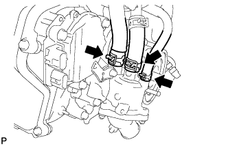
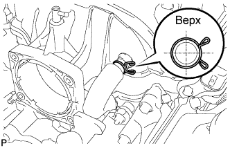
Connect the heater water inlet hose, heater water outlet hose, water inlet hose, and No. 3 water by-pass hose to the water by-pass pipe sub-assembly with the 4 clamps.
Note
Face the No. 3 water by-pass hose clip as shown in the illustration.
-
-
INSTALL GENERATOR ASSEMBLY
-
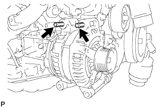
Установите генератор и с помощью торцевого ключа "TORX" E8 заверните 2 резьбовые шпильки.
- Torque:
- 10 Н*м { 102 кгс*см, 7 фунт-сила-футов }
-
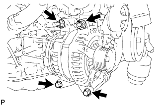
Установите генератор и закрепите 2 болтами и 2 гайками.
- Torque:
- 43 Н*м { 438 кгс*см, 32 фунт-сила-фута }
-
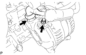
Подсоедините разъем генератора.
-
Подсоедините жгут проводов к выводу +В и закрепите его гайкой.
- Torque:
- 12 Н*м { 122 кгс*см, 9 фунт-сила-футов }
-
-
INSTALL ENGINE OIL LEVEL DIPSTICK GUIDE
-
Apply a light coat of engine oil to a new O-ring.
-
Install the new O-ring to the engine oil level dipstick guide.
-
Install the engine oil level dipstick guide with the 2 bolts.
- Torque:
- 10 N*m { 102 kgf*cm, 7 ft.*lbf }
-
Install the engine oil level dipstick.
-
-
CONNECT COOLER COMPRESSOR ASSEMBLY
-
Connect the cooler compressor assembly with the 2 stud bolts, 2 nuts and 2 bolts.
- Torque:
- for stud bolts
- 10 N*m { 102 kgf*cm, 7 ft.*lbf }
- for nuts
- 25 N*m { 255 kgf*cm, 18 ft.*lbf }
- for bolts
- 25 N*m { 255 kgf*cm, 18 ft.*lbf }
-
-
INSTALL EXHAUST MANIFOLD SUB-ASSEMBLY LH
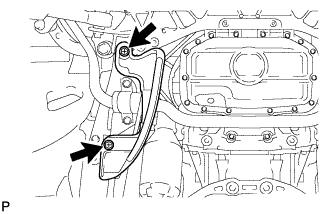
-
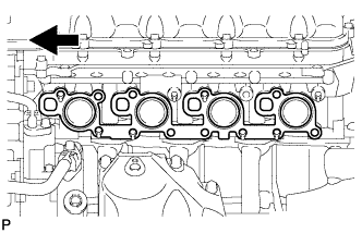
Install a new gasket as shown in the illustration.
Text in Illustration 
Front -
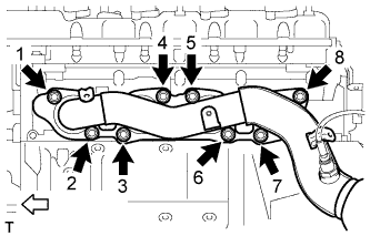
Install the exhaust manifold to the cylinder head with the new 8 nuts in the order shown in the illustration.
- Torque:
- 21 N*m { 214 kgf*cm, 15 ft.*lbf }
Text in Illustration 
Front
-
-
INSTALL NO. 2 EXHAUST MANIFOLD HEAT INSULATOR
-
Install the heat insulator with the 3 bolts.
- Torque:
- 10 N*m { 102 kgf*cm, 7 ft.*lbf }
-
Connect the sensor connector.
-
-
INSTALL NO. 2 STEERING INTERMEDIATE SHAFT ASSEMBLY
-
Установите зажим на чехол выходного отверстия рулевой колонки.
-
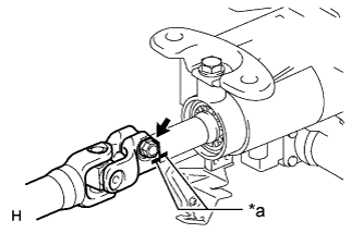
Обозначения на рисунке *a Метка Совместите метки на промежуточном валу № 2 рулевого управления и рулевой колонке.
-
Вверните болт.
- Torque:
- 35 Н*м { 360 кгс*см, 26 фунт-сила-футов }
-
-
INSTALL STEERING SLIDING YOKE WITH SHAFT SUB-ASSEMBLY (w/ VGRS)
-
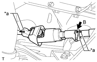
Обозначения на рисунке *a Метка Совместите метки на промежуточном валу рулевого управления № 2 в сборе и шлицевом хомуте рулевого вала в сборе.
-
Совместите сборочные метки на шлицевом хомуте рулевого вала и тяге рулевого управления с усилителем.
-
Не затягивая, вверните болт B.
Note
Не затягивайте болт.
-
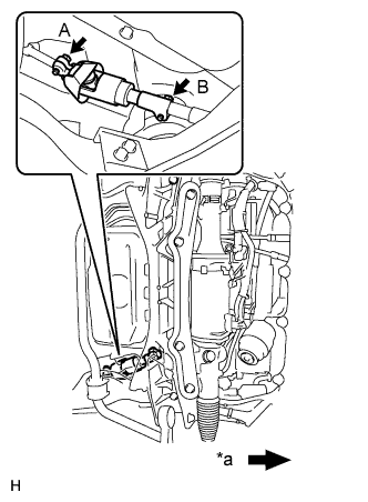
Обозначения на рисунке *a Передняя сторона автомобиля Вверните болт A и затяните болт B.
- Torque:
- 35 Н*м { 360 кгс*см, 26 фунт-сила-футов }
-
-
INSTALL STEERING SLIDING YOKE WITH SHAFT SUB-ASSEMBLY (w/o VGRS)
-
Обозначения на рисунке *a Метка Совместите метки на промежуточном валу рулевого управления № 2 и шлицевом хомуте рулевого вала в сборе.
-
Совместите сборочные метки на шлицевом хомуте рулевого вала и промежуточном валу рулевого управления.
-
Не затягивая, вверните болт B.
Note
Не затягивайте болт.
-
Обозначения на рисунке *a Передняя сторона автомобиля Вверните болт A и затяните болт B.
- Torque:
- 35 Н*м { 360 кгс*см, 26 фунт-сила-футов }
-
-
INSTALL FRONT SUSPENSION MEMBER REINFORCEMENT LH
-
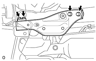
Установите левое усиление элемента передней подвески на автомобиль и закрепите его 4 болтами.
- Torque:
- 50 Н*м { 510 кгс*см, 37 фунт-сила-дюймов }
-
-
INSTALL FRONT STABILIZER BAR
-
INSTALL FRONT EXHAUST PIPE ASSEMBLY
-
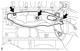
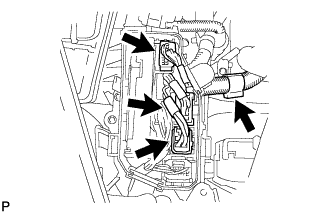
CONNECT ENGINE WIRE
-
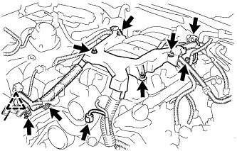
Connect the engine wire with the 4 nuts.
- Torque:
- 10 N*m { 102 kgf*cm, 7 ft.*lbf }
-
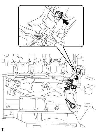
Connect the clamp and install the 2 clamp brackets with the 2 bolts.
- Torque:
- 10 N*m { 102 kgf*cm, 7 ft.*lbf }
-
Connect the intake air control valve actuator connector.
-
Connect the No. 1 vacuum switching valve connector.
-
Connect the ground wire with the bolt.
- Torque:
- 21 N*m { 214 kgf*cm, 15 ft.*lbf }
-
for Engine Room RH Side:
-
Connect the 2 clamps and install the 3 clamp brackets with the 3 bolts.
- Torque:
- 10 N*m { 102 kgf*cm, 7 ft.*lbf }
-
Connect the engine oil level sensor connector.
-
Connect the crankshaft position sensor connector.
-
Connect the starter connector and starter wire with the nut.
- Torque:
- 10 N*m { 102 kgf*cm, 7 ft.*lbf }
-
Connect the generator connector and generator wire with the nut.
- Torque:
- 12 N*m { 122 kgf*cm, 9 ft.*lbf }
-
Connect the camshaft position sensor connector.
-
Connect the engine wire connector.
-
Connect the 2 camshaft timing control motor connectors. (for Bank 2)
-
Connect the 2 VVT sensor connectors.
-
Connect the 4 ignition coil connectors.
-
Connect the camshaft timing control valve connector.
-
Connect the wires to the No. 1 engine room junction block with the 2 nuts.
- Torque:
- 13 N*m { 133 kgf*cm, 10 ft.*lbf }
-
Connect the 3 connectors to the front controller with the clamp.
-
-
for Engine Room LH Side:
-
Install the clamp bracket with the bolt.
- Torque:
- 10 N*m { 102 kgf*cm, 7 ft.*lbf }
-
Connect the 3 clamps and 3 ground wires with the 3 bolts.
- Torque:
- 10 N*m { 102 kgf*cm, 7 ft.*lbf }
-
Attach the clamp and connect the cooler compressor connector.
-
Connect the 2 camshaft timing control motor connectors. (for Bank 1)
-
Connect the engine oil pressure sensor connector.
-
Connect the engine coolant temperature sensor connector.
-
Connect the clamp and install the 2 clamp brackets with the 2 bolts.
- Torque:
- 10 N*m { 102 kgf*cm, 7 ft.*lbf }
-
Connect the No. 8 engine wire connector.
-
Connect the 2 VVT sensor connectors.
-
Connect the 4 ignition coil connectors.
-
Connect the camshaft timing control valve connector.
-
Connect the 3 ECT connectors and 4 ECM connectors.
-
Install the ECM box cover (upper).
-
-
-
INSTALL ENGINE ROOM ECU OUTLET DUCT
-
Install the engine room ECU outlet duct.
-
-
INSTALL SKID CONTROL ECU BRACKET
-
CONNECT NO. 2 RADIATOR HOSE
-
CONNECT NO. 1 RADIATOR HOSE
-
INSTALL V-RIBBED BELT
-
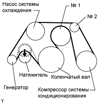
Install the V belt as shown in the illustration.
Note
Check that the drive belt is properly set to each pulley.
-
Rotate the tensioner pulley counterclockwise, and then remove the fix bar.
-
-
-
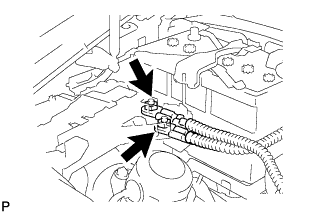
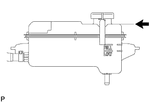
INSTALL RADIATOR RESERVOIR ASSEMBLY
-
Install the radiator reservoir assembly with the 2 bolts.
- Torque:
- 5.0 N*m { 51 kgf*cm, 44 in.*lbf }
-
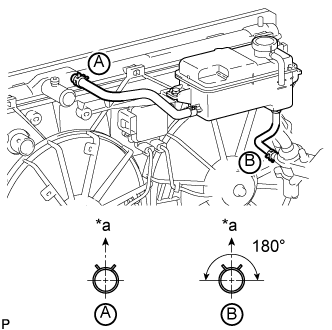
Text in Illustration *a Upper Connect the 2 reservoir hoses.
Tech Tips
The direction of the hose clamp is indicated in the illustration.
-
-
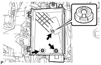
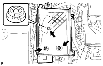
INSTALL AIR CLEANER ASSEMBLY LH
-
Install the air cleaner case LH with the 2 nuts and clip.
- Torque:
- 5.0 N*m { 51 kgf*cm, 44 in.*lbf }
-
Install the air cleaner element to the air cleaner case LH.
-
Install the air cleaner cap LH with the 2 clamps.
-
Connect the mass air flow meter connector.
-
-
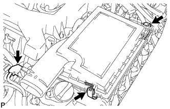
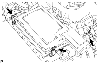
INSTALL AIR CLEANER ASSEMBLY RH
-
Install the air cleaner case RH with the 2 nuts and clip.
- Torque:
- 5.0 N*m { 51 kgf*cm, 44 in.*lbf }
-
Install the air cleaner element to the air cleaner case RH.
-
Install the air cleaner cap RH with the 2 clamps.
-
Connect the mass air flow meter connector.
-
-
INSTALL INTAKE AIR CONNECTOR PIPE
-
Совместите выступ на резонаторе воздухозаборника с вырезом кронштейна и вставьте выступ.
-
Установите патрубок подачи воздуха и закрепите 3 хомутами.
- Torque:
- для патрубка подачи воздуха и корпуса дроссельной заслонки
- 4,8 Н*м { 49 кгс*см, 42 фунт-сила-дюйма }
- для патрубка подачи воздуха и крышки воздушного фильтра
- 3,8 Н*м { 39 кгс*см, 34 фунт-сила-дюйма }
Tech Tips
-
Вставьте выступ на патрубке подачи воздуха в отверстие хомута.
-
Патрубок подачи воздуха и хомут корпуса дроссельной заслонки могут быть затянуты с моментом из диапазона 4,0-5,5 Н*м (41-56 кгс*см, 35-49 фунт-сила-дюймов), а патрубок подачи воздуха и хомут крышки воздушного фильтра – с моментом из диапазона 2,0-5,5 Н*м (20-56 кгс*см, 18-49 фунт-сила-дюймов).
-
Установите 2 зажима жгута проводов.
-
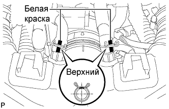
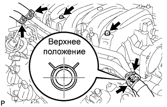
Подсоедините шланг вентиляции картера № 1 и № 2 к патрубку подачи воздуха.
Tech Tips
-
Расположите захваты хомутов, как показано на рисунке.
-
Установите хомуты так, чтобы они находились в пределах меток, нанесенных на шланге краской.
-
-
-
INSTALL NO. 1 AIR CLEANER INLET
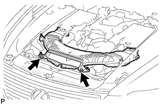
-
Совместите отверстия с местами соединений A и подсоедините входной патрубок воздушного фильтра № 1.
-
Установите входной патрубок воздушного фильтра № 1 и закрепите его 2 болтами.
- Torque:
- 5,0 Н*м { 51 кгс*см, 44 фунт-сила-дюйма }
-
-
INSTALL ENGINE UNDER COVER REAR LH
-
Установите левую заднюю защиту картера двигателя и закрепите ее 2 винтами.
-
-
INSTALL ENGINE UNDER COVER REAR RH
Tech Tips
Детали с правой стороны устанавливаются в той же последовательности, что и с левой стороны.
-
INSTALL BATTERY TRAY
-
Install the battery tray with the 3 bolts.
- Torque:
- 5.4 N*m { 55 kgf*cm, 48 in.*lbf }
-
Install the battery and battery insulator.
-
-
INSTALL BATTERY CLAMP SUB-ASSEMBLY
-
Install the battery clamp and 2 clamp bolts with the nut.
- Torque:
- 5.4 N*m { 55 kgf*cm, 48 in.*lbf }
-
-
ADD ENGINE OIL
-
Add fresh oil.
Standard engine oil Oil grade Oil Viscosity (SAE) API grade SL "energy-conserving", SM "energy-conserving", SN "resource-conserving" or ILSAC multigrade engine oil 0W-20
5W-20
5W-30
10W-30
API grade SL, SM or SN multigrade engine oil 15W-40
20W-50
Standard capacity Item Specified Condition Drain and refill without oil filter change 8.4 liters (8.9 US qts, 7.4 Imp. qts) Drain and refill with oil filter change 8.6 liters (9.1 US qts, 7.6 Imp. qts) Dry fill 10.2 liters (10.8 US qts, 9.0 Imp. qts) -
Install the oil filler cap.
-
Close the oil filler cap service hole cover.
-
-
ADD ENGINE COOLANT
Общая емкость 11,8 литра (12,5 кварты США, 10,4 английской кварты) CAUTION:
Не снимайте пробку расширительного бачка радиатора, пока двигатель и радиатор не остынут. Выброс горячей охлаждающей жидкости и пара под давлением может стать причиной серьезных ожогов.
Note
Перед добавлением охлаждающей жидкости установите выключатель системы кондиционирования в положение OFF (ВЫКЛ).
-
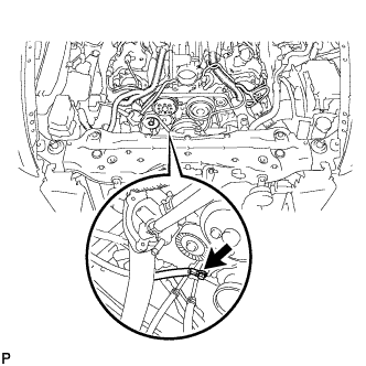
Затяните пробку сливного крана радиатора.
-
Затяните 2 пробки сливных кранов блока цилиндров.
- Torque:
- 13 Н*м { 133 кгс*см, 10 фунт-сила-футов }
-
Долейте в расширительный бачок радиатора фирменную жидкость с увеличенным сроком замены (SLLC) от компании Тойота.
Объем Приблизительно 5,0 литра (5,3 кварты США, 4,4 английской кварты) Tech Tips
-
Автомобили Тойота охлаждающей жидкостью TOYOTA SLLC на заводе. Во избежание повреждения системы охлаждения двигателя или других технических проблем разрешается использовать только охлаждающую жидкость "TOYOTA Super Long Life Coolant" или аналогичную высококачественную охлаждающую жидкость на основе этиленгликоля (а не на силикатной, аминовой, нитритной или борнокислой основе), изготовленную по гибридной технологии органических кислот с длительным сроком годности (охлаждающая жидкость, изготовленная по гибридной технологии органических кислот, состоит из низкофосфатных соединений и органических кислот).
-
Обратитесь к уполномоченному дилеру Toyota, в ремонтную мастерскую или к квалифицированному специалисту с необходимым оборудованием за подробной информацией.
-
Время открывания термостата можно проверить, сжав входной патрубок радиатора рукой и убедившись, что охлаждающая жидкость поступает в шланг.
-
-
Затем долейте охлаждающую жидкость в бачок радиатора до отметки "FULL".
-
Несколько раз сожмите рукой патрубки радиатора № 1 и № 2, затем проверьте уровень охлаждающей жидкости.
Если уровень охлаждающей жидкости недостаточен, добавьте жидкость.
-
С помощью торцевого шестигранного ключа на 6 мм установите вентиляционную пробку.
- Torque:
- 1,5 Н*м { 15 кгс*см, 13 фунт-сила-дюймов }
-
Выпустите воздух из системы охлаждения.
Note
Перед запуском двигателя для прогрева установите выключатель системы кондиционирования в положение OFF (ВЫКЛ).
-
При двигателе, работающем на холостом ходу в течение приблизительно 10 минут, убедитесь, что уровень хладагента остается на отметке "FULL", при необходимости добавляя охлаждающую жидкость.
-
Дав двигателю поработать на холостом ходу в течение 10 минут, долейте охлаждающую жидкость до линии B.
Объем Приблизительно 2,5-3,5 л (2,6-3,7 кварты США, 2,2-3,1 английской кварты) Обозначения на рисунке Линия B Tech Tips
Линия В находится в нижней внутренней части наливной горловины.
-
Закройте пробку расширительного бачка радиатора и поддерживайте частоту вращения коленчатого вала двигателя в диапазоне 1500-2000 об/мин в течение 5 минут.
CAUTION:
-
Работайте в защитных перчатках.
-
Будьте осторожны: патрубок радиатора горячий.
-
Не прикасайтесь к вентиляторам радиатора.
Tech Tips
Время открывания термостата можно проверить, сжав шланг радиатора № 1 рукой и убедившись, что SLLC поступает в шланг.
-
-
-
Остановите двигатель и подождите, пока охлаждающая жидкость остынет до температуры окружающего воздуха.
-
Проверьте уровень охлаждающей жидкости.
Если уровень охлаждающей жидкости ниже уровня "FULL", добавьте охлаждающую жидкость до отметки "FULL".
-
-
CONNECT CABLE TO NEGATIVE BATTERY TERMINAL
Note
When disconnecting the cable, some systems need to be initialized after the cable is reconnected Click here.
-
INSPECT FOR OIL LEAK
-
Start the engine. Make sure that there are no oil leaks from the area that was worked on.
-
-
INSPECT FOR COOLANT LEAK
CAUTION:
Do not remove the radiator reservoir cap while the engine and radiator are still hot. Pressurized, hot engine coolant and steam may be released and cause serious burns.
Note
Before each inspection, turn the A/C switch OFF.
-
Fill the radiator with coolant and attach a radiator cap tester.
-
Warm up the engine.
-
Using the radiator cap tester, increase the pressure inside the radiator to 118 kPa (1.2 kgf/cm2, 17 psi), and check that the pressure does not drop.
If the pressure drops, check the hoses, radiator and water pump for leaks. If no external leaks are found, check the heater core, cylinder block and head.
-
-
INSPECT FOR EXHAUST GAS LEAK
-
При наличии утечки газа затяните соединения в местах утечки. При необходимости замените поврежденные детали.
-
-
CHECK ENGINE OIL LEVEL
-
Warm up the engine, stop the engine and wait 5 minutes. The oil level should be between the dipstick's low level mark and full level mark.
If low, check for leakage and add oil up to the full level mark.
Note
Do not fill engine oil above the full level mark.
Tech Tips
A certain amount of engine oil will be consumed while driving. In the following situations, oil consumption may increase, and engine oil may need to be refilled in between oil maintenance intervals.
-
When the engine is new, for example directly after purchasing the vehicle or after replacing the engine.
-
If low quality oil or oil of an inappropriate viscosity is used.
-
When driving at high engine speed or with a heavy load, (when towing, or), when driving while accelerating or decelerating frequently.
-
When leaving the idling for a long time, or when driving frequently through heavy traffic.
When judging the amount of oil consumption, keep in mind that the oil may have become diluted, making it difficult to judge the true level accurately.
-
-
-
INSTALL FRONT SUSPENSION MEMBER PROTECTOR LOWER
-
Install the front suspension member protector lower with the 8 bolts.
- Torque:
- 5.5 N*m { 56 kgf*cm, 49 in.*lbf }
-
-
INSTALL NO. 2 ENGINE UNDER COVER
-
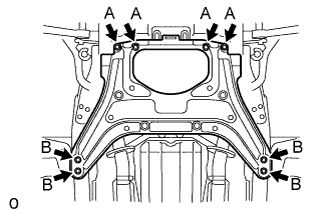
Install the No. 2 engine under cover with the 8 bolts.
- Torque:
- for Bolt A
- 10 N*m { 102 kgf*cm, 7 ft.*lbf }
- for Bolt B
- 27 N*m { 275 kgf*cm, 20 ft.*lbf }
-
-
INSTALL NO. 1 ENGINE UNDER COVER
-
Установите защиту картера двигателя № 1 и закрепите ее 13 винтами и 7 фиксаторами.
-
-
INSTALL ENGINE ROOM SIDE COVER RH
-
Установите правую боковую крышку моторного отсека и закрепите ее 5 фиксаторами.
-
-
INSTALL ENGINE ROOM SIDE COVER LH
-
Установите левую боковую крышку моторного отсека и закрепите ее 5 фиксаторами.
-
-
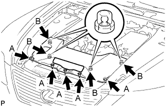
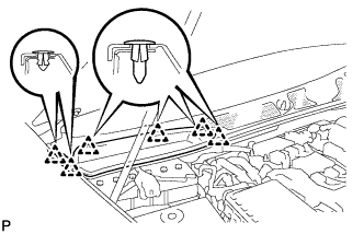
INSTALL AIR CLEANER INLET COVER SUB-ASSEMBLY
-
Введите в зацепление 4 фиксатора В.
Note
-
Убедитесь, что фиксаторы введены в зацепление надежно.
-
Фиксаторы могут повредится, если вводить их в зацепление с чрезмерным усилием или посредством постукивания по их верхней части.
-
-
Установите крышку входного патрубка воздушного фильтра и закрепите ее 5 фиксаторами А.
-
-
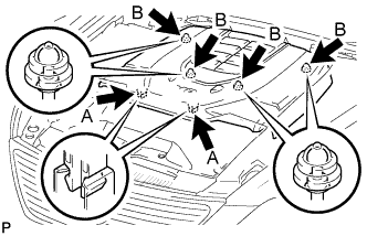
INSTALL V-BANK COVER SUB-ASSEMBLY
-
Сдвинув крышку по направлению от передней к задней части автомобиля, чтобы ввести в зацепление 2 фиксатора A, введите в зацепление 4 фиксатора B и установите декоративную крышку V-образного двигателя.
Note
-
Убедитесь, что фиксаторы введены в зацепление надежно.
-
Фиксаторы могут повредится, если вводить их в зацепление с чрезмерным усилием или посредством постукивания по их верхней части.
-
-
-
INSTALL COWL TOP VENTILATOR LOUVER RH
-
Введите в зацепление 6 фиксаторов и установите правую вентиляционную решетку в верхней части кожуха.
Note
Если правая вентиляционная решетка в верхней части кожуха установлена ненадлежащим образом, в моторный отсек может проникать вода, что приведет к возникновению неисправностей. Поэтому убедитесь, что правая вентиляционная решетка в верхней части кожуха установлена надлежащим образом.
-