ВПУСКНОЙ КОЛЛЕКТОР УСТАНОВКА
-
INSTALL INTAKE MANIFOLD
-
Install 2 new gaskets to the intake manifold.
-
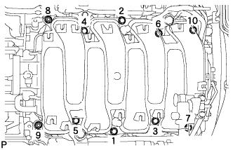
Temporarily install the intake manifold with the 2 nuts and 8 bolts. Then tighten the 2 nuts and 8 bolts uniformly in the order shown in the illustration.
- Torque:
- 21 N*m { 214 kgf*cm, 15 ft.*lbf }
-
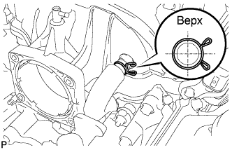
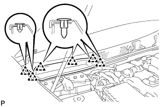
Connect the No.1 ventilation hose to the intake manifold.
Note
Face the claws of the clips as shown in the illustration.
-
-
INSTALL VACUUM SWITCHING VALVE ASSEMBLY
-
Install the vacuum switching valve assembly with the bolt.
- Torque:
- 21 N*m { 214 kgf*cm, 15 ft.*lbf }
-
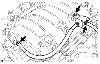
Connect the fuel vapor feed hose to the intake manifold.
-
Connect the No.2 fuel vapor feed hose to the vacuum switching valve assembly.
-
-
INSTALL WATER BY-PASS PIPE SUB-ASSEMBLY
-
Install the water by-pass pipe sub-assembly to the intake manifold with the 2 bolts.
-
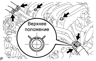
Connect the heater water inlet hose, heater water outlet hose, water inlet hose, and No. 3 water by-pass hose to the water by-pass pipe sub-assembly with the 4 clamps.
Note
Face the No. 3 water by-pass hose clip as shown in the illustration.
-
-
CONNECT ENGINE WIRE
-
Connect the cooler compressor connector.
-
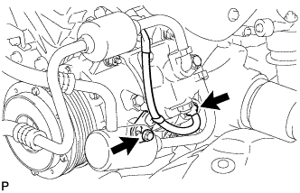
Connect the wire harness bracket with the bolt.
- Torque:
- 10 N*m { 102 kgf*cm, 7 ft.*lbf }
-
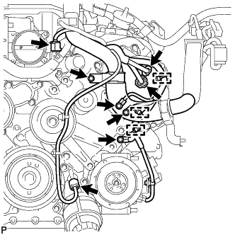
Install the clamp bracket with the bolt.
- Torque:
- 10 N*m { 102 kgf*cm, 7 ft.*lbf }
-
Connect the 3 clamps and 3 ground wires with the 3 bolts.
- Torque:
- 10 N*m { 102 kgf*cm, 7 ft.*lbf }
-
Connect the 2 camshaft timing control motor connectors (for Bank 1).
-
Connect the oil pressure sensor connector.
-
Connect the engine coolant temperature sensor connector.
-
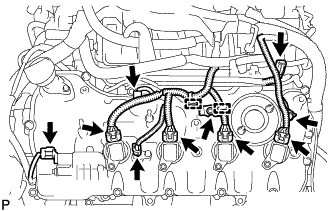
Connect the clamp and install the 2 clamp brackets with the 2 bolts.
- Torque:
- 10 N*m { 102 kgf*cm, 7 ft.*lbf }
-
Connect the No. 8 engine wire connector.
-
Connect the 2 VVT sensor connectors.
-
Connect the 4 ignition coil connectors.
-
Connect the camshaft timing control valve connector.
-
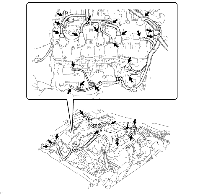
Connect the engine wire harness with the 4 nuts.
- Torque:
- 10 N*m { 102 kgf*cm, 7 ft.*lbf }
-
Install the 3 engine wire harness clamp brackets with the 3 bolts.
- Torque:
- 10 N*m { 102 kgf*cm, 7 ft.*lbf }
-
Connect the engine wire to the fusible link block assembly with the nut.
- Torque:
- 13 N*m { 127 kgf*cm, 10 ft.*lbf }
-
Connect the 7 engine wire harness clamps.
-
Connect the +B terminal of the generator assembly with the nut.
- Torque:
- 12 N*m { 122 kgf*cm, 9 ft.*lbf }
-
Connect the engine wire harness connector.
-
-
INSTALL AIR CLEANER ASSEMBLY LH
-
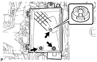
Install the air cleaner case LH with the 2 nuts and clip.
- Torque:
- 5.0 N*m { 51 kgf*cm, 44 in.*lbf }
-
Install the air cleaner element to the air cleaner case LH.
-
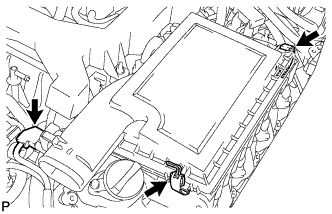
Install the air cleaner cap LH with the 2 clamps.
-
Connect the mass air flow meter connector.
-
-
INSTALL AIR CLEANER ASSEMBLY RH
-
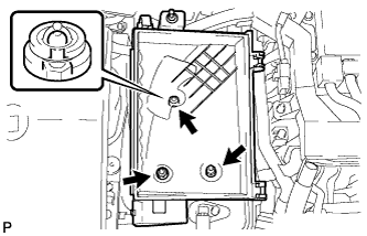
Install the air cleaner case RH with the 2 nuts and clip.
- Torque:
- 5.0 N*m { 51 kgf*cm, 44 in.*lbf }
-
Install the air cleaner element to the air cleaner case RH.
-
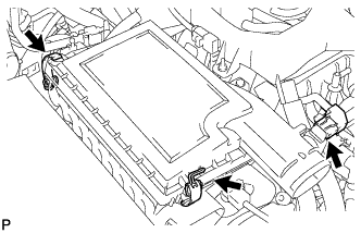
Install the air cleaner cap RH with the 2 clamps.
-
Connect the mass air flow meter connector.
-
-
INSTALL THROTTLE BODY
-
CONNECT CABLE TO NEGATIVE BATTERY TERMINAL
Note
When disconnecting the cable, some systems need to be initialized after the cable is reconnected Click here.
-
INSTALL ENGINE ROOM SIDE COVER RH
-
Установите правую боковую крышку моторного отсека и закрепите ее 5 фиксаторами.
-
-
INSTALL ENGINE ROOM SIDE COVER LH
-
Установите левую боковую крышку моторного отсека и закрепите ее 5 фиксаторами.
-
-
INSTALL FRONT SUSPENSION MEMBER PROTECTOR LOWER
-
Install the front suspension member protector lower with the 8 bolts.
- Torque:
- 5.5 N*m { 56 kgf*cm, 49 in.*lbf }
-
-
INSTALL NO. 2 ENGINE UNDER COVER
-
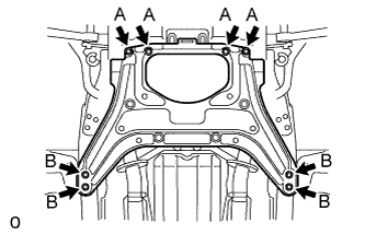
Install the No. 2 engine under cover with the 8 bolts.
- Torque:
- for Bolt A
- 10 N*m { 102 kgf*cm, 7 ft.*lbf }
- for Bolt B
- 27 N*m { 275 kgf*cm, 20 ft.*lbf }
-
-
INSTALL COWL TOP VENTILATOR LOUVER RH
-
Введите в зацепление 6 фиксаторов и установите правую вентиляционную решетку в верхней части кожуха.
Note
Если правая вентиляционная решетка в верхней части кожуха установлена ненадлежащим образом, в моторный отсек может проникать вода, что приведет к возникновению неисправностей. Поэтому убедитесь, что правая вентиляционная решетка в верхней части кожуха установлена надлежащим образом.
-