REAR SUNSHADE SYSTEM Only Front Switch Cannot Operate Rear Sunshade
DESCRIPTION
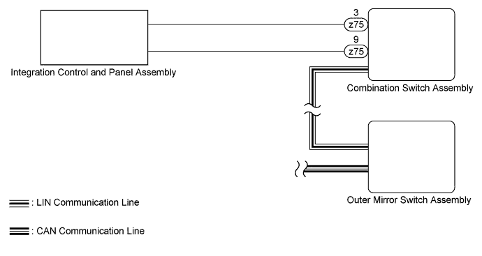
A rear sunshade switch signal is sent from the integration control and panel assembly to the combination switch assembly. Then the signal is sent through LIN communication to the outer mirror switch assembly, which then sends the signal through CAN communication to the luggage room junction block assembly (rear junction block ECU), and the rear sunshade operates.
WIRING DIAGRAM
INSPECTION PROCEDURE
PROCEDURE
-
CHECK FOR DTC
-
Clear the DTCs Click here.
-
Check for DTCs Click here.
Result Result Proceed to No DTC is output A DTC U1114 is output (for LHD) B DTC U1114 is output (for RHD) C DTC U1127 is output D
B 
GO TO CAN COMMUNICATION SYSTEM Click here
C
GO TO CAN COMMUNICATION SYSTEM Click here
D
GO TO LIN COMMUNICATION SYSTEM Click here
A 
-
-
READ VALUE USING INTELLIGENT TESTER (CENTER CONSOLE SWITCH)
-
Use the Data List to check if the rear sunshade switch is functioning properly Click here.
Center Console Switch Tester Display Measurement Item/Range Normal Condition Diagnostic Note Rear Shade Switch Rear sunshade switch / ON or OFF ON: Rear sunshade switch pressed
OFF: Rear sunshade switch not pressed
- OK Rear sunshade raises or lowers.
NG 
INSPECT INTEGRATION CONTROL AND PANEL ASSEMBLY Click here
OK
-
-
CHECK COMBINATION SWITCH ASSEMBLY
-
Temporarily replace the combination switch assembly with a new one or normally functioning one Click here.
-
Check the rear sunshade system operate normally Click here.
OK Rear sunshade raises or lowers.
NG
REPLACE OUTER MIRROR SWITCH ASSEMBLY Click here
OK 
END (COMBINATION SWITCH ASSEMBLY IS DEFECTIVE)
-
-
INSPECT INTEGRATION CONTROL AND PANEL ASSEMBLY
-
Remove the integration control and panel assembly Click here.
-
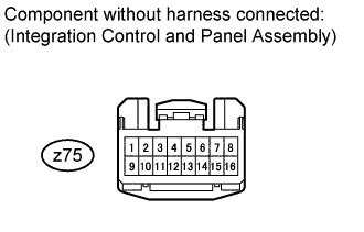
Measure the resistance according to the value(s) in the table below.
Standard resistance Tester Connection Switch Condition Specified Condition z75-3 - z75-9 Rear sunshade switch pushed Below 200 Ω z75-3 - z75-9 Rear sunshade switch not pushed 10 kΩ or higher
NG
REPLACE INTEGRATION CONTROL AND PANEL ASSEMBLY Click here
OK
REPLACE COMBINATION SWITCH ASSEMBLY Click here
-