POWER MIRROR CONTROL SYSTEM Power Mirrors do not Return to Memorized Position
SYSTEM DESCRIPTION
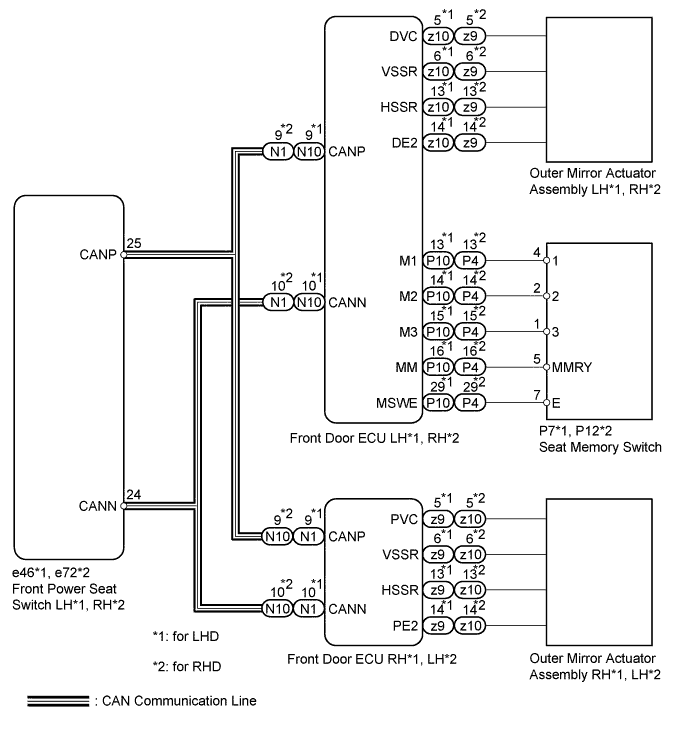
When the seat memory M1, M2 or M3 switch is pressed, the front power seat switch (for driver side) memory's driver and passenger seat mirror position signal is sent through the CAN communication line to the front door ECU LH and RH. The front door ECU LH and RH then activate the mirror control motors to move the mirrors to the previously recorded positions.
WIRING DIAGRAM
INSPECTION PROCEDURE
PROCEDURE
-
CHECK DTC
-
Use the intelligent tester to check if the CAN communication system is functioning normally.
Result Result Proceed to CAN DTC is not output A CAN DTC is output (for LHD) B CAN DTC is output (for RHD) C
B 
GO TO CAN COMMUNICATION SYSTEM Click here
C
GO TO CAN COMMUNICATION SYSTEM Click here
A 
-
-
CHECK POWER MIRROR CONTROL FUNCTION
-
Check that the mirror surface positions of the outer rear view mirror LH and RH can be moved using the outer mirror switch.
OK Mirror surface positions of the outer rear view mirror LH and RH can be moved using the outer mirror switch.
NG
REPLACE OUTER MIRROR SWITCH ASSEMBLY Click here
OK
-
-
CHECK SEAT MEMORY SWITCH FUNCTION (MIRROR MEMORY FUNCTION)
-
Check that the outer rear view mirror LH and RH positions can be memorized using the seat memory switch.
OK Outer rear view mirror LH and RH positions can be memorized using seat memory switch.
NG
GO TO FRONT POWER SEAT CONTROL SYSTEM Click here
OK
-
-
READ VALUE USING INTELLIGENT TESTER (MIRROR POSITION SENSOR)
-
Check the Data List for proper functioning of the mirror position sensor.
Driver Door Tester Display Measurement Item/Display Normal Condition Diagnostic Note Mirror Vertical Sensor voltage Mirror vertical sensor voltage / MIN: 0 V, MAX: 5 V Within range from 0 to 5 V - Mirror Horizontal Sensor Voltage Mirror horizontal sensor voltage / MIN: 0 V, MAX: 5 V Within range from 0 to 5 V - Passenger Door Tester Display Measurement Item/Display Normal Condition Diagnostic Note Mirror Vertical Sensor voltage Mirror vertical sensor voltage / MIN: 0 V, MAX: 5 V Within range from 0 to 5 V - Mirror Horizontal Sensor Voltage Mirror horizontal sensor voltage / MIN: 0 V, MAX: 5 V Within range from 0 to 5 V - OK The value is changed by manual operation. Result Result Proceed to NG (for driver side) A OK (for driver side) B NG (for passenger side) C OK (for passenger side) D
B
REPLACE FRONT DOOR ECU (for Driver Side) Click here
C 
CHECK FRONT DOOR ECU (for Passenger Side) Click here
D
REPLACE FRONT DOOR ECU (for Passenger Side) Click here
A
-
-
CHECK FRONT DOOR ECU (for Driver Side)
-

for LHD:
-
Measure the voltage according to the value(s) in the table below.
Standard voltage Tester Connection Condition Specified Condition z10-5 (DVC) - z10-14 (DE2) Power switch ON (IG) 3.5 to 5.5 V -
Measure the resistance according to the value(s) in the table below.
Standard resistance Tester Connection Condition Specified Condition z10-14 (DE2) - Body ground Always Below 1 Ω
-
-

for RHD:
-
Measure the voltage according to the value(s) in the table below.
Standard voltage Tester Connection Condition Specified Condition z9-5 (DVC) - z9-14 (DE2) Power switch ON (IG) 3.5 to 5.5 V -
Measure the resistance according to the value(s) in the table below.
Standard resistance Tester Connection Condition Specified Condition z9-14 (DE2) - Body ground Always Below 1 Ω
-
NG
REPLACE FRONT DOOR ECU (for Driver Side) Click here
OK 
REPLACE OUTER MIRROR ACTUATOR ASSEMBLY (for Driver Side) Click here
-
-
CHECK FRONT DOOR ECU (for Passenger Side)
-
for LHD:
-
Measure the voltage according to the value(s) in the table below.
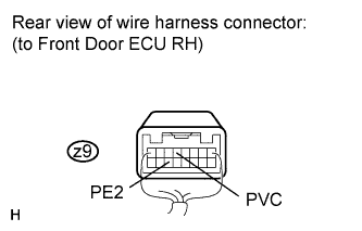
Standard voltage Tester Connection Condition Specified Condition z9-5 (PVC) - z9-14 (PE2) Power switch ON (IG) 3.5 to 5.5 V -
Measure the resistance according to the value(s) in the table below.
Standard resistance Tester Connection Condition Specified Condition z9-14 (PE2) - Body ground Always Below 1 Ω
-
-
for RHD:
-
Measure the voltage according to the value(s) in the table below.
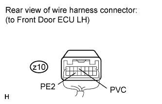
Standard voltage Tester Connection Condition Specified Condition z10-5 (PVC) - z10-14 (PE2) Power switch ON (IG) 3.5 to 5.5 V -
Measure the resistance according to the value(s) in the table below.
Standard resistance Tester Connection Condition Specified Condition z10-14 (PE2) - Body ground Always Below 1 Ω
-
NG
REPLACE FRONT DOOR ECU (for Passenger Side) Click here
OK
REPLACE OUTER MIRROR ACTUATOR ASSEMBLY (for Passenger Side) Click here
-