WINDSHIELD GLASS REMOVAL

-
PRECAUTION
Note
After turning the power switch off, waiting time may be required before disconnecting the cable from the auxiliary battery terminal. Therefore, make sure to read the disconnecting the cable from the auxiliary battery terminal notice before proceeding with work Click here.
-
REMOVE LUGGAGE COMPARTMENT MAT SUB-ASSEMBLY (w/ Spare Tire)

-
REMOVE DECK BOARD ASSEMBLY (w/o Spare Tire)

-
REMOVE DECK TRIM SIDE BOARD LH (w/o Spare Tire)
-

Detach the 2 clips and remove the deck trim side board LH.
-
-
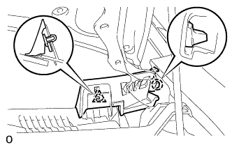
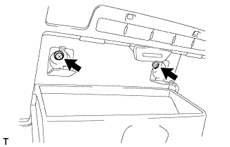
REMOVE BATTERY SERVICE HOLE COVER LH
-

Text in Illustration *A for Standard *B for Ottoman *1 Fastening Tape Detach the clip, fastening tape and remove the battery service hole cover LH.
-
-
DISCONNECT CABLE FROM AUXILIARY BATTERY NEGATIVE TERMINAL
CAUTION:
Wait at least 90 seconds after disconnecting the cable from the negative (-) battery terminal to prevent airbag and seat belt pretensioner activation.
Note
When disconnecting the cable, some systems need to be initialized after the cable is reconnected Click here.
-
REMOVE FRONT WIPER ARM LH
-
Remove the nut, wiper arm and blade.
-
-
REMOVE FRONT WIPER ARM RH
-
Remove the nut, wiper arm and blade.
-
-
REMOVE FRONT FENDER TO COWL SIDE SEAL LH
-
Detach the clip and claw, and then remove the cowl side seal LH.
-
-
REMOVE FRONT FENDER TO COWL SIDE SEAL RH
Tech Tips
Use the same procedures described for the LH side.
-
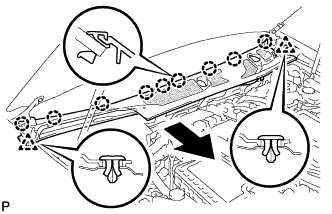
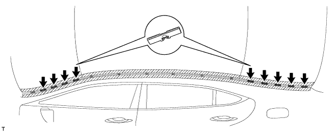
REMOVE HOOD TO COWL TOP SEAL
-
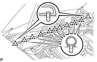
Using a clip remover, detach the 11 clips and remove the hood to cowl top seal.
-
-
REMOVE COWL TOP VENTILATOR LOUVER RH (for LHD)
-
Remove the 6 clips and cowl top ventilator louver RH.
-
-
REMOVE COWL TOP VENTILATOR LOUVER LH (for RHD)
-
Remove the 6 clips and cowl top ventilator louver RH.
-
-
REMOVE COWL TOP VENTILATOR LOUVER PROTECTOR LH
-
Detach the clip and claw.
-
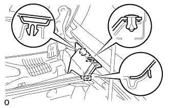
Detach the guide and remove the cowl top ventilator louver protector LH.
-
-
REMOVE COWL TOP VENTILATOR LOUVER SUB-ASSEMBLY
-
Using a clip remover, detach the 2 clips.
-
Detach the 9 claws.
-
Remove the cowl top ventilator louver sub-assembly.
-
-
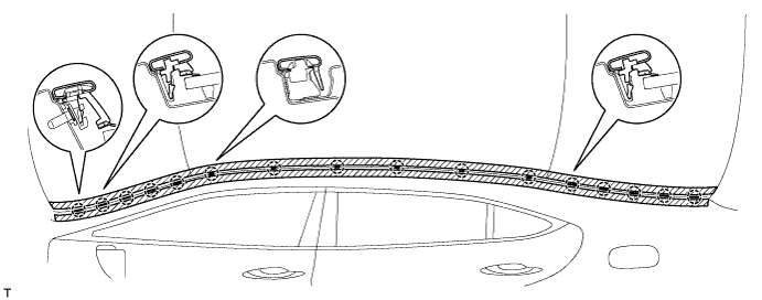
REMOVE CENTER ROOF DRIP SIDE FINISH MOULDING LH
-
Put protective tape around the center roof drip side finish moulding.
-
for Standard Body:
Using a moulding remover, detach the 16 clips and remove the center roof drip side finish moulding LH.
-
for Long Body:
Using a moulding remover, detach the 17 clips and remove the center roof drip side finish moulding.
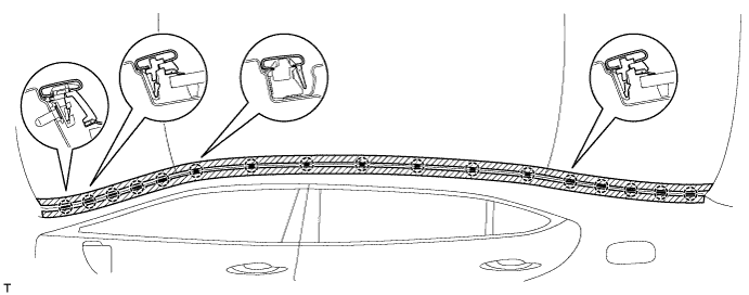
Note
-
Do not remove the clips from the vehicle body.
-
If the clips are damaged or removed accidentally, replace them.
-
-
-
REMOVE CENTER ROOF DRIP SIDE FINISH MOULDING RH
Tech Tips
Use the same procedures described for the LH side.
-
REMOVE NO. 2 WINDSHIELD OUTSIDE MOULDING CLIP
Tech Tips
Perform the following procedure if replacing the No. 2 outside windshield moulding clip.
-
Remove the No. 2 outside windshield moulding clip.
-
Remove the No. 2 moulding clip.
-
-
REMOVE NO. 1 WINDSHIELD OUTSIDE MOULDING CLIP
Tech Tips
Use the same procedures described for the No. 2 windshield outside moulding clip.
-
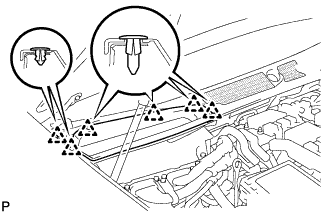
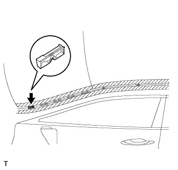
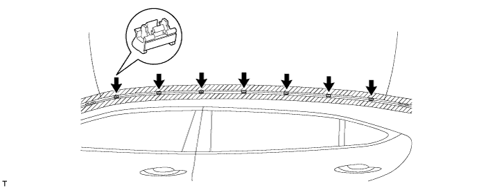
REMOVE NO. 2 ROOF DRIP SIDE FINISH MOULDING CLIP
Tech Tips
Perform the following procedure if replacing the No. 2 roof drip side finish moulding clips.
-
Remove the 9 No. 2 roof drip side finish moulding clips.
-
-
REMOVE NO. 3 WINDSHIELD OUTSIDE MOULDING CLIP
Tech Tips
Perform the following procedure if replacing the No. 3 outside windshield moulding clip.
-
Put a 4 mm (0.16 in.) drill bit into a drill.
-
Wind tape around the drill bit approximately 5 mm (0.20 in.) from the tip of the drill.
Tech Tips
Tape the 4 mm (0.16 in.) drill bit to prevent the drill bit from going too deep.
-
Lightly press the drill against the rivets, drill off the flanges of the rivets, and remove the 10 rivets.
Note
-
Pressing the drill too firmly will cause the rivet to turn and result in the rivet not being drilled through.
-
Do not pry the rivets with the drill, because this may cause damage to the installation holes of the rivets or the drill bit.
-
Be careful of the drilled rivets as they may become hot.
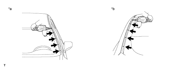
Text in Illustration *a Front Side *b Rear Side -
-
Using a vacuum cleaner, remove the rivet fragments and shavings from the drilled areas.
-
-
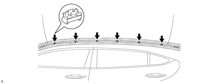
REMOVE NO. 1 ROOF DRIP SIDE FINISH MOULDING CLIP
Tech Tips
Perform the following procedure if replacing the No. 1 roof drip side finish moulding clips.
-
for Standard Body:
Remove the 6 No. 1 roof drip side finish moulding clips.
-
for Long Body:
Remove the 7 No. 1 roof drip side finish moulding clips.
-
-
REMOVE FRONT PILLAR GARNISH LH
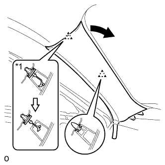
Text in Illustration *1 Front Pillar Garnish Clip
-
Pull the upper part of the front pillar garnish LH toward the inside of the cabin and detach the 2 clips.
Tech Tips
Make the front pillar garnish LH hang down from the front pillar garnish clip.
-
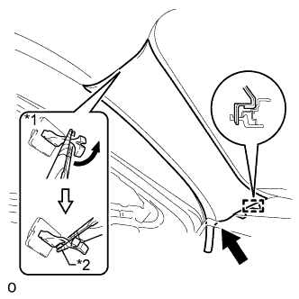
Text in Illustration *1 Front Pillar Garnish Clip *2 Protective Tape Turn the end of the front pillar garnish clip 90° with needle-nose pliers and remove it from the front pillar garnish LH.
Note
-
Front pillar garnish clips are reusable if they are not removed from the vehicle and have no damage.
-
Replace the front pillar garnish clips with new ones if they are removed from the vehicle.
Tech Tips
Tape the tips of the needle-nose pliers before use.
-
-
Pull the front pillar garnish LH to detach the guide and remove it.
-
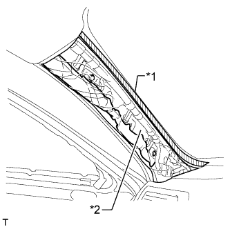
Text in Illustration *1 Adhesive Tape *2 Protective Cover Protect the curtain shield airbag assembly LH.
Completely cover the curtain shield airbag assembly LH with a cloth or nylon sheet and secure the ends of the cover with adhesive tape as shown in the illustration.
Note
Cover the curtain shield airbag assembly LH with a protective cover as soon as the front pillar garnish LH is removed.
-
-
REMOVE FRONT PILLAR GARNISH RH
Tech Tips
Use the same procedure described for the LH side.
-
REMOVE VISOR BRACKET COVER
Tech Tips
Use the same procedure to remove the cover on the other side.
-
Using moulding remover D, detach the 4 claws and remove the visor bracket cover.
-
-
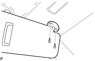
REMOVE VISOR ASSEMBLY LH
-
Remove the 2 screws and visor assembly LH.
-
-
REMOVE VISOR ASSEMBLY RH
Tech Tips
Use the same procedure described for the LH side.
-
REMOVE VISOR HOLDER
Tech Tips
Use the same procedure to remove the holder on the other side.
-
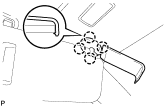
Turn the visor holder approximately 45° and pull it out as shown in the illustration.
-
Detach the 2 claws and remove the visor holder.
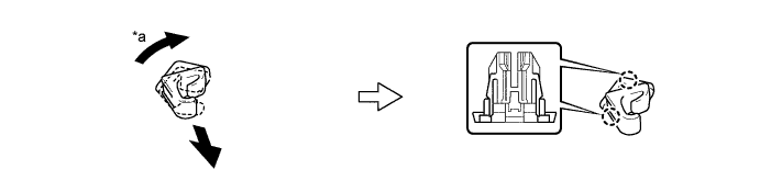
Text in Illustration *a 45° - -
-
-
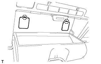
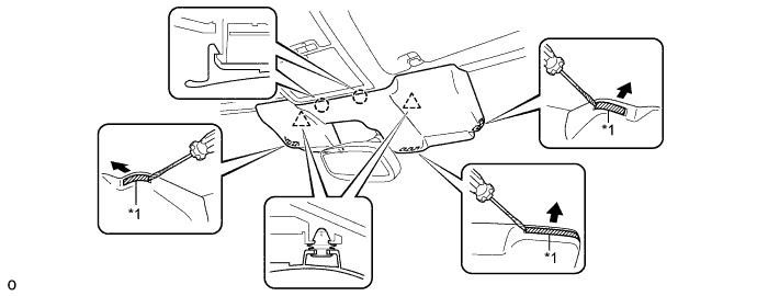
REMOVE ASSIST GRIP SUB-ASSEMBLY
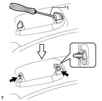
Text in Illustration *1 Protective Tape Tech Tips
Use the same procedure for all the assist grips.
-
Using a screwdriver, detach the 4 claws and remove the 2 assist grip covers.
Tech Tips
Tape the screwdriver tip before use.
-
Detach the 2 clips and remove the assist grip sub-assembly.
-
-
REMOVE MAP LIGHT ASSEMBLY
-
Using a screwdriver, detach the 2 claws and 2 covers.
Tech Tips
Tape the screwdriver tip before use.
-
Remove the 2 screws.
-
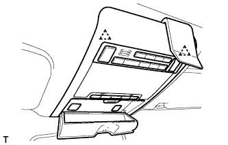
Using a moulding remover, detach the 2 clips.
-
Disconnect the connectors and remove the map light assembly.
-
-
REMOVE RAIN SENSOR COVER (w/o Driver Monitor Camera)
-
Pull the stopper in the direction shown in the illustration.
-
Detach the 2 claws and remove the rain sensor cover.
-
-
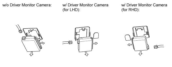
REMOVE RAIN SENSOR COVER (w/ Driver Monitor Camera)
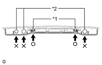
Text in Illustration *1 Clip *2 Camera Note
When removing the rain sensor cover, do not apply force to the object recognition camera areas labeled "X".
-
Pull the stopper in the direction shown in the illustration.
Text in Illustration *1 Stopper - - -
While being careful not to apply force to the camera areas, detach the 2 clips and 2 claws and remove the rain sensor cover.
-
-
REMOVE INNER REAR VIEW MIRROR ASSEMBLY (w/o Automatic High Beam System, Adaptive High Beam System)
-
Disconnect the connector.
-
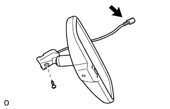
Using a T20 "TORX" socket wrench, remove the screw and inner rear view mirror.
-
-
REMOVE INNER REAR VIEW MIRROR ASSEMBLY (w/ Automatic High Beam System, Adaptive High Beam System)
Note
-
Do not touch the camera lens (built into the inner rear view mirror assembly) with a bare hand.
-
Do not allow anything to adhere to the camera lens (built into the inner rear view mirror assembly).
-
Do not apply strong impacts to the inner rear view mirror assembly.
-
Do not allow any liquids to get on the inner rear view mirror assembly.
-
Disconnect the connector.
-
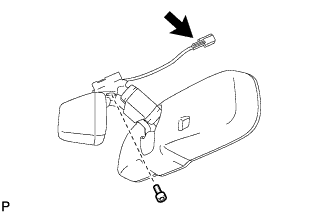
Using a T20 "TORX" socket wrench, remove the screw and inner rear view mirror.
-
-
REMOVE OBJECT RECOGNITION CAMERA (w/ Driver Monitor Camera)
-
Partially remove the roof headlining assembly.
Tech Tips
It is not necessary to completely remove the roof headlining. Slightly lower the front section of the roof headlining so that the object recognition camera can be removed.
-
Disconnect the 3 connectors.
-
Detach the 2 wire harness clamps.
-
Detach the claw and disconnect the connector clamp.
-
Remove the 3 bolts.
-
Detach the clip and remove the object recognition camera.
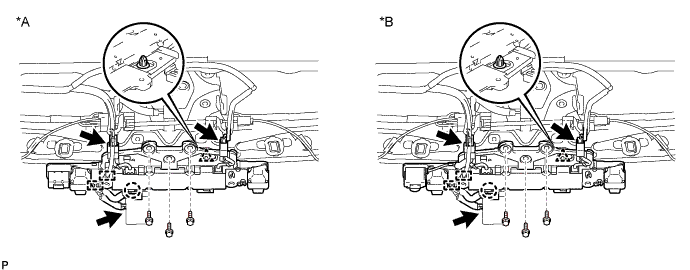
Text in Illustration *A w/o Night View System *B w/ Night View System
-
-
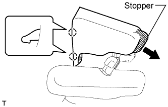
REMOVE RAIN SENSOR
-
Pull the stopper in the direction shown in the illustration, and release the lock.
-
Disconnect the connector, and remove the rain sensor.
-
-
REMOVE ROOF HEADLINING
-
Partially remove the roof headlining.
Tech Tips
It is not necessary to completely remove the roof headlining. Slightly lower the front section of the roof headlining so that the windshield glass can be removed in a later step.
for Standard Body, refer to the following procedures Click here.
for Long Body, refer to the following procedures Click here.
-
-
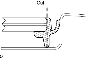
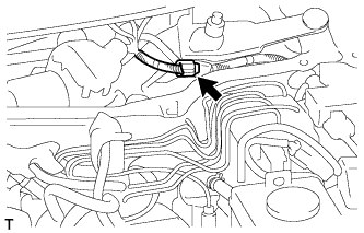
REMOVE UPPER WINDSHIELD OUTSIDE MOULDING
-
Using a knife, cut off the moulding as shown in the illustration.
Note
Be careful not to damage the vehicle body.
-
Pull the shaded area shown in the illustration by hand to remove the windshield outside moulding.
Tech Tips
Make a partial cut in the moulding. Then pull and remove it by hand.
-
-
REMOVE WINDSHIELD GLASS
-
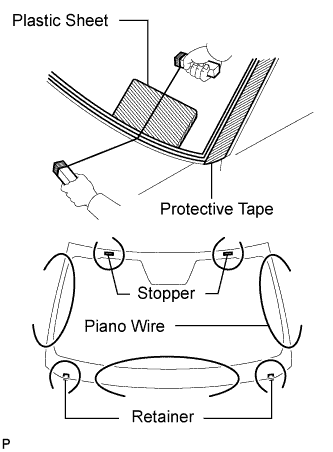
Apply protective tape to the outer surface of the vehicle body to prevent scratches.
-
From the interior, insert a piano wire between the vehicle body and glass as shown in the illustration.
-
Tie objects that can serve as handles (for example, wooden blocks) to both wire ends.
Note
-
When separating the glass from the vehicle, be careful not to damage the vehicle's paint or interior / exterior ornaments.
-
To prevent the instrument panel from being scratched when removing the glass, place a plastic sheet between the piano wire and instrument panel.
-
-
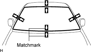
Place matchmarks over the glass and vehicle body on the locations indicated in the illustration.
Tech Tips
Matchmarks do not need to be placed if not reusing the glass.
-
w/ Windshield Deicer System:
Disconnect the windshield deicer connector.
-
Cut through the adhesive by pulling the piano wire around the glass.
Note
Leave as much adhesive on the vehicle body as possible when removing the glass.
-
Disconnect the stoppers.
-
Using suction cups, remove the glass.
-
-
REMOVE NO. 2 WINDSHIELD GLASS STOPPER
-
Using a scraper, remove the 2 stoppers.
-
-
REMOVE WINDSHIELD GLASS RETAINER
-
Using a scraper, remove the 2 retainers.
-
-
REMOVE WINDSHIELD GLASS ADHESIVE DAM
-
Using a scraper, remove the dam.
-
-
REMOVE WINDSHIELD GLASS SEAL
-
Using a scraper, remove the seal.
-
-
CLEAN WINDSHIELD GLASS
-
Using a scraper, remove the damaged stoppers, dam and adhesive sticking to the glass.
-
Clean the outer circumference of the glass with non-residue solvent.
Note
-
Do not touch the glass surface after cleaning it.
-
Be careful not to damage the glass.
-
Even if using new glass, clean the glass with non-residue solvent.
-
-
-
REMOVE NO. 1 WINDSHIELD GLASS STOPPER
-
Remove the No. 1 windshield glass stoppers.
-
-
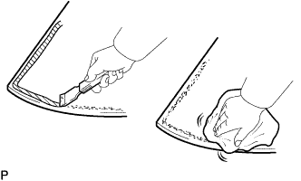
CLEAN VEHICLE BODY
-
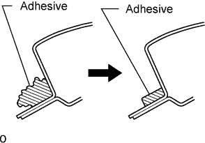
Clean and shape the contact surface of the vehicle body.
-
On the contact surface of the vehicle body, use a knife to cut away excess adhesive as shown in the illustration.
Note
Be careful not to damage the vehicle body.
Tech Tips
Leave as much adhesive on the vehicle body as possible.
-
Clean the contact surface of the vehicle body with cleaner.
Tech Tips
Even if all the adhesive has been removed, clean the vehicle body.
-
-