RADIO ANTENNA CORD REMOVAL

Tech Tips
-
Use the same procedure for RHD and LHD vehicles.
-
The procedure listed below is for LHD vehicles.
-
PRECAUTION
CAUTION:
After turning the power switch off, waiting time may be required before disconnecting the cable from the auxiliary battery negative (-) terminal. Therefore, make sure to read the disconnecting the cable from the auxiliary battery negative (-) terminal notices before proceeding with work Click here.
-
REMOVE LUGGAGE COMPARTMENT MAT SUB-ASSEMBLY (w/ Spare Tire)

-
REMOVE DECK BOARD ASSEMBLY (w/o Spare Tire)

-
REMOVE DECK TRIM SIDE BOARD LH (w/o Spare Tire)
-

Detach the 2 clips and remove the deck trim side board LH.
-
-
REMOVE BATTERY SERVICE HOLE COVER LH
-

Text in Illustration *A for Standard *B for Ottoman *1 Fastening Tape Detach the clip, fastening tape and remove the battery service hole cover LH.
-
-
DISCONNECT CABLE FROM AUXILIARY BATTERY NEGATIVE TERMINAL
Note
When disconnecting the cable, some systems need to be initialized after the cable is reconnected Click here.
-
REMOVE INSTRUMENT PANEL FINISH PANEL END LH
-
Pull the front part of the instrument panel finish panel end LH to detach the 6 clips.
-
Pull the instrument panel finish panel end LH to detach 3 clips and remove the instrument panel finish panel end LH.
-
-
REMOVE INSTRUMENT PANEL FINISH PANEL END RH
Tech Tips
Use the same procedure described for the LH side.
-
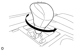
REMOVE SHIFT LEVER KNOB SUB-ASSEMBLY
-
Twist the shift lever knob sub-assembly in the direction indicated by the arrow and remove it.
-
-
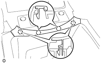
REMOVE NO. 3 BOX PANEL
-
Detach the 4 claws and remove the No. 3 box panel.
-
-
REMOVE UPPER REAR CONSOLE PANEL SUB-ASSEMBLY
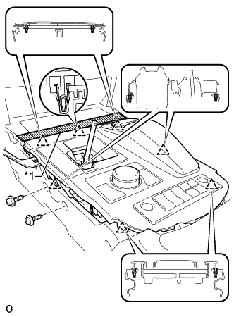
Text in Illustration *1 Protective Tape
-
Apply protective tape as shown in the illustration.
-
Move the shift lever to N.
-
Remove the 2 screws.
-
Detach the 6 clips and remove the upper rear console panel sub-assembly.
-
Disconnect each connector and detach each wire harness clamp.
-
-
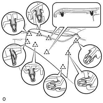
REMOVE UPPER INSTRUMENT CLUSTER FINISH PANEL
-
Apply protective tape as shown in the illustration.
-
Hold the opposite end with one hand as shown in the illustration so that the clip can be firmly pushed.
-
Insert a screwdriver at the location shown in the illustration, and then push the lower clip on the backside of the upper instrument cluster finish panel towards the rear of the vehicle to detach it.
Note
At this time, all the clips may become detached and the upper instrument cluster finish panel may suddenly come off. Therefore, slowly push on the clip to detach it.
Tech Tips
-
Tape the screwdriver tip before use.
-
The upper clip of the upper instrument cluster finish panel may become detached at the same time.
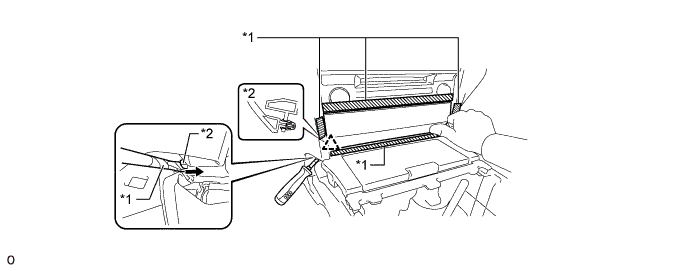
Text in Illustration *1 Protective Tape *2 Lower Clip 
Rear of the Vehicle - - -
-
Insert a screwdriver at the location shown in the illustration, and then push the lower clip on the backside of the upper instrument cluster finish panel towards the rear of the vehicle to detach it.
Note
-
Slowly push on the clip to detach it.
-
At this time, all the clips may become detached and the upper instrument cluster finish panel may suddenly come off. Therefore, place one hand on the upper instrument cluster finish panel as shown in the illustration.
Tech Tips
-
Tape the screwdriver tip before use.
-
The upper clip of the upper instrument cluster finish panel may become detached at the same time.
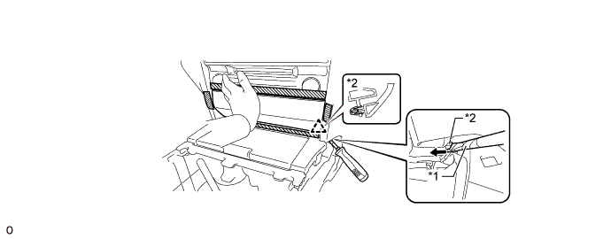
Text in Illustration *1 Protective Tape *2 Lower Clip Rear of the Vehicle - - -
-
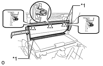
Text in Illustration *1 Protective Tape 
Upper Instrument Cluster Finish Panel Edge Insert moulding remover A between the upper instrument cluster finish panel and lower No. 1 instrument panel finish panel, and between the upper instrument cluster finish panel and lower No. 2 instrument panel finish panel to detach the 3 upper clips and remove the upper instrument cluster finish panel.
Note
If pressure is applied to the edge of the upper instrument cluster finish panel using moulding remover A, the surface may be damaged. Therefore, insert moulding remover A deep past the edge of the upper instrument cluster finish panel to detach the clips.
Tech Tips
If any of the upper clips have become detached during the previous procedure, detach the remaining clips to remove the upper instrument cluster finish panel.
-
-
REMOVE UPPER CONSOLE PANEL SUB-ASSEMBLY
-
Disconnect the connector.
-
Detach the 6 clips and remove the upper console panel sub-assembly.
-
-
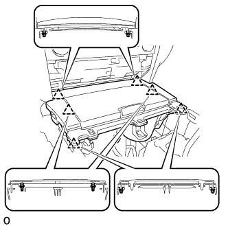
REMOVE LOWER NO. 1 INSTRUMENT PANEL FINISH PANEL
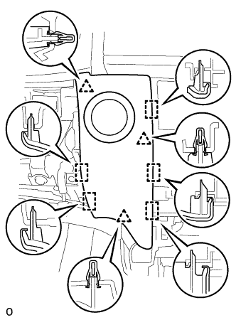
-
Detach the 4 clips and 5 guides and remove the lower No. 1 instrument panel finish panel.
-
Disconnect the connector.
-
-
REMOVE LOWER NO. 2 INSTRUMENT PANEL FINISH PANEL
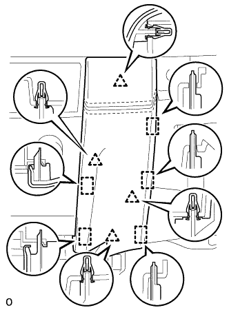
-
Detach the 4 clips and 5 guides and remove the lower No. 2 instrument panel finish panel.
-
-
REMOVE MULTI-MEDIA MODULE RECEIVER ASSEMBLY
-
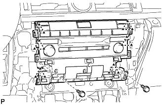
Remove the 2 bolts.
-
Detach the 6 clips and pull out the multi-media module receiver assembly with bracket.
-
Disconnect the connectors and remove the multimedia module receiver assembly with bracket.
-
-
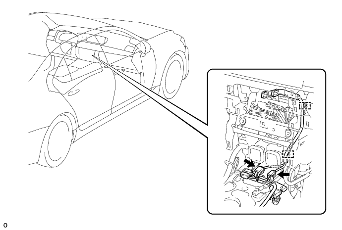
REMOVE ANTENNA CORD SUB-ASSEMBLY
-
Disconnect each connector.
-
Detach the clamp and remove the antenna cord sub-assembly.
-
-
REMOVE FRONT CONSOLE BOX ASSEMBLY
-
w/o Rear Entertainment System:
-
for 5-Passenger with Ottoman:
-
w/ Disc Player:
-
-
REMOVE FRONT SEAT ASSEMBLY RH
-
REMOVE REAR SEAT ASSEMBLY
-
for Power Seat:
-
for 4-Passenger with Ottoman:
-
for 5-Passenger with Ottoman:
-
for Fixed Seat:
-
-
REMOVE ROOF SIDE GARNISH INNER RH
-
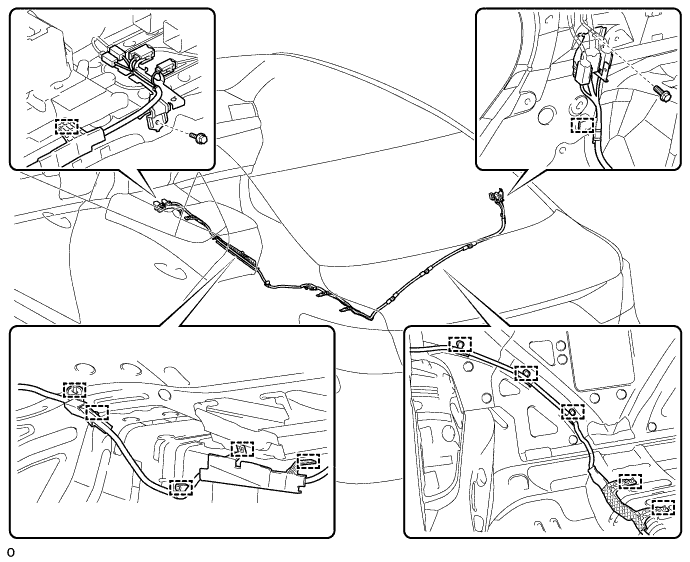
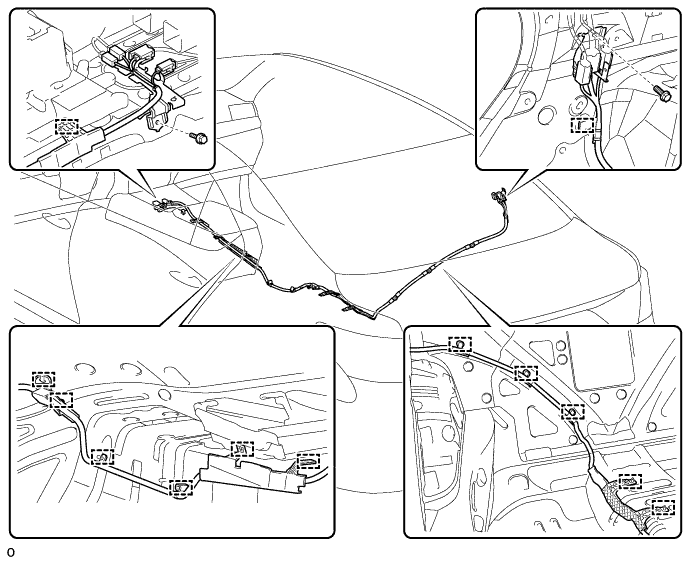
REMOVE NO. 2 ANTENNA CORD SUB-ASSEMBLY
-
for Standard Body:
-
Disconnect each connector.
-
Remove the 2 bolts.
-
Detach the 12 clamps and remove the No. 2 antenna cord sub-assembly.
-
-
for Long Body:
-
Disconnect each connector.
-
Remove the 2 bolts.
-
Detach the 13 clamps and remove the No. 2 antenna cord sub-assembly.
-
-
-
REMOVE ROOF HEADLINING ASSEMBLY
-
for Standard Body:
-
for Long Body:
-
-
REMOVE NO. 3 ANTENNA CORD SUB-ASSEMBLY
-
Disconnect each connector.
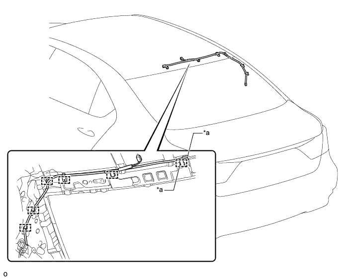
Text in Illustration *a w/ Digital Audio Broadcasting - - -
Detach the 6 clamps and remove the No. 3 antenna cord sub-assembly.
-