COMBINATION METER INSTALLATION

Tech Tips
-
Use the same procedure for RHD and LHD vehicles.
-
The procedure listed below is for LHD vehicles.
-
INSTALL COMBINATION METER ASSEMBLY
-
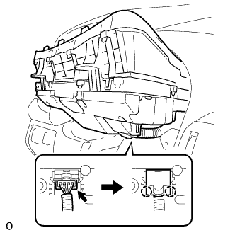
Connect the connector and attach the 2 claws to close the connector cover.
-
Install the combination meter assembly with the 4 screws.
-
-
INSTALL STEERING COLUMN COVER (w/o Driver Monitor Camera)
-
Attach the claw to install the upper steering column cover.
-
Attach the 4 clips to install the upper steering column cover onto the instrument cluster finish panel.
-
Attach the 2 claws to install the lower steering column cover.
Note
Do not damage the tilt and telescopic switch.
-
Install the 3 screws.
-
-
INSTALL STEERING COLUMN COVER (w/ Driver Monitor Camera)
-
Connect the driver monitor connector.
-
Attach the claw to install the upper steering column cover.
-
Attach the 4 clips to install the upper steering column cover onto the instrument cluster finish panel.
-
Attach the 2 claws to install the lower steering column cover.
Note
Do not damage the tilt and telescopic switch.
-
Install the 3 screws.
-
-
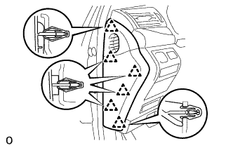
INSTALL NO. 2 INSTRUMENT CLUSTER FINISH PANEL SUB-ASSEMBLY
-
Connect the 2 connectors.
-
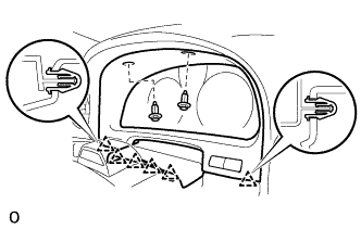
Attach the 6 clips to install the No. 2 instrument cluster finish panel sub-assembly.
-
Install the 2 clips.
-
-
INSTALL NO. 1 INSTRUMENT PANEL SAFETY PAD SUB-ASSEMBLY
-
Connect each connector.
-
Attach the 5 clips and claw to install the No. 1 instrument panel safety pad sub-assembly.
-
Install the screw <C> and bolt.
-
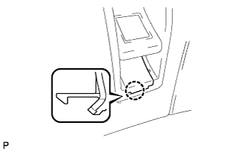
Attach the claw to install the switch base hole cover to the No. 1 instrument panel safety pad sub-assembly.
-
-
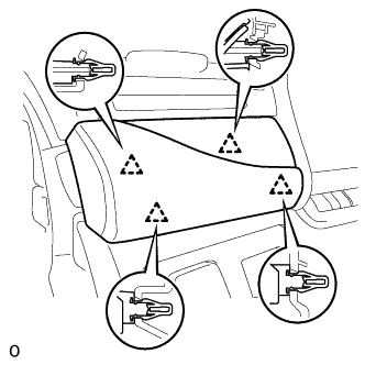
INSTALL INSTRUMENT PANEL ORNAMENT
-
Connect the connector.
-
Attach the 4 clips to install the instrument panel ornament.
-
-
INSTALL INSTRUMENT SIDE PANEL LH
-
Attach the 6 clips to install the instrument side panel LH.
-
-
CONNECT CABLE TO AUXILIARY BATTERY NEGATIVE TERMINAL
Note
When disconnecting the cable, some systems need to be initialized after the cable is reconnected Click here.
-
ENABLE AUTOAWAY/RETURN FUNCTION
-
Restore the autoaway/return function setting to the previous condition by changing the customize parameter Click here.
-
-
INSTALL BATTERY SERVICE HOLE COVER LH
-

Text in Illustration *A for Standard *B for Ottoman Attach the battery service hole cover LH with the clip and fastening tape.
-
-
INSTALL DECK TRIM SIDE BOARD LH (w/o Spare Tire)
-

Attach the 2 clips to install the deck trim side board LH.
-
-
INSTALL DECK BOARD ASSEMBLY (w/o Spare Tire)

-
INSTALL LUGGAGE COMPARTMENT MAT SUB-ASSEMBLY (w/ Spare Tire)
