BRAKE PEDAL STROKE SENSOR INSTALLATION

Tech Tips
-
Use the same procedure for the RHD and LHD vehicles.
-
The procedure listed below is for the LHD vehicles.
Note
While the battery is connected, even if the power switch is OFF, the brake control system activates when the brake pedal is depressed or the door courtesy switch turns on. Therefore during servicing of the brake system components, do not operate the brake pedal or open/close the doors while the battery is connected.
-
INSTALL BRAKE PEDAL STROKE SENSOR ASSEMBLY
Note
Do not drop the sensor. If the sensor has been dropped, replace the sensor with a new one.
-
When installing a new brake pedal stroke sensor assembly:
Install a new brake pedal stroke sensor assembly as follows.
Note
Do not break the sensor lever set pin before installing the brake pedal stroke sensor with the bolts.
-
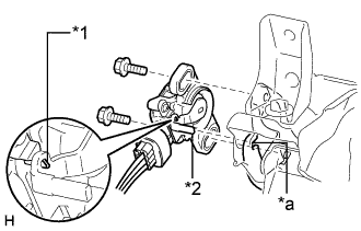
Text in Illustration *1 Pin *2 Lever *a Groove Connect the sensor connector.
-
Install a new sensor with the 2 bolts.
- Torque:
- 8.5 N*m { 87 kgf*cm, 75 in.*lbf }
Note
-
Engage the sensor lever with the brake pedal groove.
-
Check that there is no foreign matter attached to the contact surface of the sensor.
-
Check that the tip of the sensor lever is protruding from the brake pedal groove.
-
Firmly depress the brake pedal and break the sensor lever set pin.
-
Remove the broken lever set pin.
-
-
When reusing the brake pedal stroke sensor assembly:
-
Connect the sensor connector.
Note
Do not drop the sensor. If the sensor has been dropped, replace the sensor with a new one.
-
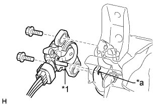
Text in Illustration *1 Lever *a Groove Temporarily install the sensor with the 2 bolts.
Note
-
Engage the sensor lever with the brake pedal groove.
-
Check that there is no foreign matter attached to the contact surface of the sensor.
-
-
Connect the cable to the negative battery terminal.
-
Connect the intelligent tester to the DLC3.
-
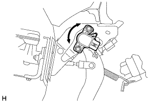
Turn the power switch ON (IG). Reading the value of the stroke sensor shown on the data monitor, turn the sensor slowly to the right and left to adjust the output voltage to the standard voltage.
Standard voltage Tester Display Measurement Item/Range Normal Condition Diagnostic Note Stroke Sensor Stroke sensor / min.: 0 V, max.: 5 V When brake pedal is released: 0.7 to 1.3 V - -
Tighten the 2 bolts.
- Torque:
- 8.5 N*m { 87 kgf*cm, 75 in.*lbf }
Note
Do not depress the brake pedal after turning the power switch ON (IG).
-
Disconnect the cable from the negative battery terminal.
-
Disconnect the intelligent tester.
-
-
-
INSTALL NO. 1 INSTRUMENT PANEL SAFETY PAD SUB-ASSEMBLY
-
CONNECT CABLE TO AUXILIARY BATTERY NEGATIVE TERMINAL
Note
-
Reset the AUTO TILT AWAY function setting to the previous condition by changing the customize parameter Click here.
-
When disconnecting the cable, some systems need to be initialized after the cable is reconnected Click here.
-
-
INSTALL BATTERY SERVICE HOLE COVER LH
-

Text in Illustration *A for Standard *B for Ottoman Attach the battery service hole cover LH with the clip and fastening tape.
-
-
INSTALL DECK TRIM SIDE BOARD LH (w/o Spare Tire)
-

Attach the 2 clips to install the deck trim side board LH.
-
-
INSTALL DECK BOARD ASSEMBLY (w/o Spare Tire)

-
INSTALL LUGGAGE COMPARTMENT MAT SUB-ASSEMBLY (w/ Spare Tire)

-
CHECK SRS WARNING LIGHT
-
CHECK AND CLEAR DTC
-
PERFORM LINEAR VALVE OFFSET LEARNING