LANE-KEEPING ASSIST SYSTEM, Diagnostic DTC:U1119, U1119, U1120

| DTC Code | DTC Name |
|---|---|
| U1119 | Lost Communication with Object Recognition ECU (CAN) |
| U1119 | Lost Communication with Object Recognition ECU (Serial) |
| U1120 | Lost Communication with Object Recognition Camera |
DESCRIPTION
When a serial communication stop between the object recognition ECU and object recognition camera is detected, DTCs U1119 and U1120 are output.
When a CAN communication stop between the object recognition ECU and driving support ECU is detected, DTC U1119 is output.
| DTC Code | DTC Detection Condition | Trouble Area |
|---|---|---|
| U1119 | While power switch is ON (IG), serial communication stop between object recognition ECU and object recognition camera continues for 1 sec. or more |
|
| U1119 | While power switch is ON (IG), communication stop between object recognition ECU and driving support ECU continues for 1 sec. or more |
|
| U1120 | While power switch is ON (IG), serial communication stop between object recognition camera and object recognition ECU continues for 1 sec. or more |
|
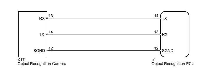
WIRING DIAGRAM
INSPECTION PROCEDURE
PROCEDURE
-
READ VALUE USING INTELLIGENT TESTER (OBJECT RECOGNITION ECU)
-
Use the Data List to check if the communication with object recognition ECU Click here.
Radar Cruise Tester Display Measurement Item/Range Normal Condition Diagnostic Note Communication with Object Recognition ECU Communication with object recognition ECU signal/AVAIL or FAIL AVAIL: Communication is normal
FAIL: Communication is malfunctioning
- Tech Tips
As the "Communication with Object Recognition ECU" item monitors the CAN communication condition, distinguishing between a CAN communication malfunction and serial communication malfunction is possible. If a CAN communication malfunction may be present, proceed to the DIAGNOSTIC TROUBLE CODE CHART.
Result Result Proceed to "Communication with Object Recognition ECU" is "AVAIL" A "Communication with Object Recognition ECU" is "FAIL" (for LHD) B "Communication with Object Recognition ECU" is "FAIL" (for RHD) C
B 
GO TO CAN COMMUNICATION SYSTEM Click here
C
GO TO CAN COMMUNICATION SYSTEM Click here
A 
-
-
CHECK HARNESS AND CONNECTOR (OBJECT RECOGNITION ECU - OBJECT RECOGNITION CAMERA)
-
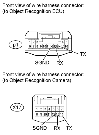
Disconnect the p1 ECU connector.
-
Disconnect the X17 camera connector.
-
Measure the resistance according to the value(s) in the table below.
Standard Resistance Tester Connection Condition Specified Condition p1-12 (SGND) - X17-12 (SGND) Always Below 1 Ω p1-13 (RX) - X17-14 (TX) Always Below 1 Ω p1-14 (TX) - X17-13 (RX) Always Below 1 Ω p1-13 (RX) - Body ground Always 10 kΩ or higher p1-12 (SGND) - Body ground Always 10 kΩ or higher p1-14 (TX) - Body ground Always 10 kΩ or higher
NG
REPAIR OR REPLACE HARNESS OR CONNECTOR
OK
-
-
REPLACE OBJECT RECOGNITION CAMERA
-
Replace the object recognition camera Click here.
NEXT
-
-
ADJUST OBJECT RECOGNITION CAMERA
-
Adjust the object recognition camera Click here.
NEXT
-
-
CHECK FOR DTC
-
Clear the DTCs Click here.
-
Check for DTCs Click here.
OK DTC U1119 and U1120 are not output.
NG
REPLACE OBJECT RECOGNITION ECU Click here
OK 
END (OBJECT RECOGNITION CAMERA IS DEFECTIVE)
-
-
REPLACE OBJECT RECOGNITION ECU
-
Replace the object recognition ECU Click here.
NEXT
-
-
ADJUST OBJECT RECOGNITION CAMERA
-
Adjust the object recognition camera Click here.
NEXT
-
-
CHECK FOR DTC
-
Clear the DTCs Click here.
-
Check for DTCs Click here.
OK DTC U1119 and U1120 are not output.
NG
REPLACE DRIVING SUPPORT ECU Click here
OK
END (OBJECT RECOGNITION ECU IS DEFECTIVE)
-