LANE-KEEPING ASSIST SYSTEM, Diagnostic DTC:C1A05

| DTC Code | DTC Name |
|---|---|
| C1A05 | Stop Light Switch Circuit |
DESCRIPTION
When the brake pedal is depressed, the stop light switch assembly sends a brake pedal operation signal to the driving support ECU. After receiving this signal, the driving support ECU cancels the radar cruise control system. When the driving support ECU detects a problem in the stop light switch circuit, DTC C1A05 is stored.
| DTC Code | DTC Detection Condition | Trouble Area |
|---|---|---|
| C1A05 |
|
|
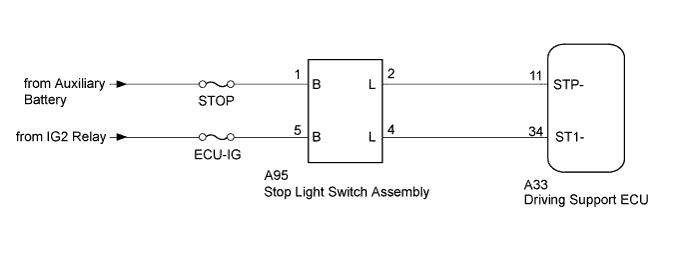
WIRING DIAGRAM
INSPECTION PROCEDURE
Note
-
Inspect the fuses for circuits related to this system before performing the following inspection procedure.
-
When replacing the driving support ECU, always replace it with a new one and be sure to perform initialization Click here. If an ECU which was installed to another vehicle is used, the information stored in the ECU will not match the information from the vehicle, and as a result, a DTC may be stored.
PROCEDURE
-
CHECK STOP LIGHT OPERATION
-
Turn the power switch on (IG), depress the brake pedal and check that the stop lights illuminate.
OK The stop lights illuminate when the brake pedal is depressed and turn off when the brake pedal is released.
NG 
GO TO LIGHTING SYSTEM Click here
OK 
-
-
CHECK HARNESS AND CONNECTOR (STOP LIGHT SWITCH ASSEMBLY - DRIVING SUPPORT ECU AND AUXILIARY BATTERY)
-
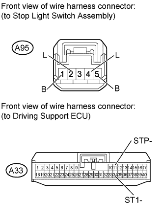
Disconnect the A95 stop light switch assembly connector.
-
Disconnect the A33 driving support ECU connector.
-
Measure the resistance according to the value(s) in the table below.
Standard Resistance Tester Connection Condition Specified Condition A95-2 (L) - A33-11 (STP-) Always Below 1 Ω A95-4 (L) - A33-34 (ST1-) Always Below 1 Ω A95-2 (L) - Body ground Always 10 kΩ or higher A95-4 (L) - Body ground Always 10 kΩ or higher -
Measure the voltage according to the value(s) in the table below.
Standard Voltage Tester Connection Condition Specified Condition A95-1 (B) - Body ground Always 11 to 14 V A95-5 (B) - Body ground Power switch on (IG) 11 to 14 V Power switch off Below 1 V
NG
REPAIR OR REPLACE HARNESS OR CONNECTOR
OK
-
-
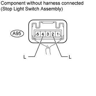
CHECK STOP LIGHT SWITCH ASSEMBLY
-
Disconnect the A33 driving support ECU connector.
-
Measure the voltage according to the value(s) in the table below.
Standard Voltage Tester Connection Condition Specified Condition A95-2 (L) - Body ground Brake pedal released Below 1 V A95-4 (L) - Body ground Brake pedal released Below 1 V A95-2 (L) - Body ground Brake pedal pushed 11 to 14 V A95-4 (L) - Body ground Brake pedal pushed 11 to 14 V
NG
REPLACE STOP LIGHT SWITCH ASSEMBLY Click here
OK
-
-
CHECK FOR DTC
-
Connect the intelligent tester to the DLC3.
-
Turn the power switch to on (IG) and turn the intelligent tester on.
-
Clear the DTCs Click here.
-
Make sure the following conditions are met:
Tech Tips
If the detection conditions are not met, the system cannot detect malfunctions.
-
Radar cruise control system: The vehicle is being driven at a speed of approximately 50 km/h (31 mph) or more and the ACC main switch is on.
-
Lane-keeping assist system: The vehicle is being driven at a speed of approximately 50 km/h (31 mph) or more and the lane-keeping assist main switch is on.
-
The brake pedal is depressed for 1 second or more.
-
-
Enter the following menus: Utility / All Codes.
-
Check DTCs.
Result Result Proceed to DTCs are not output. A DTCs are output. B Only C1A05 is output. C
B
GO TO DTC OF OTHER COMPONENTS
C
REPLACE DRIVING SUPPORT ECU Click here
A 
USE SIMULATION METHOD TO CHECK Click here
-