AUDIO AND VISUAL SYSTEM (for Radio and Display Type), Diagnostic DTC:B15D8

| DTC Code | DTC Name |
|---|---|
| B15D8 | Monitor Disconnected |
DESCRIPTION
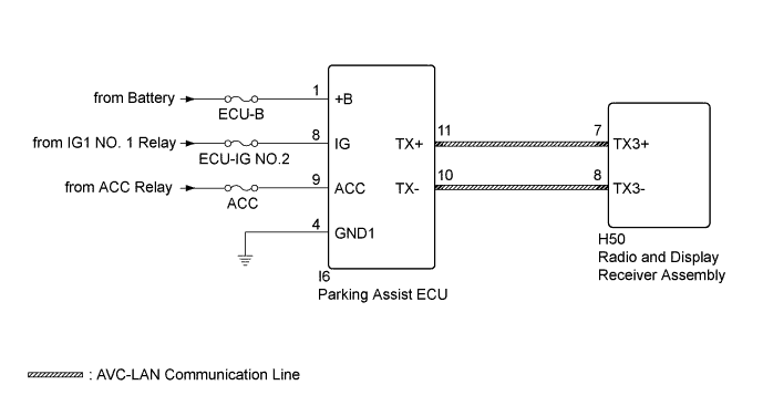
The parking assist ECU and radio and display receiver assembly are connected by an AVC-LAN communication line. When an AVC-LAN communication error occurs between the radio and display receiver assembly and parking assist ECU, these DTCs will be stored.
| DTC Code | DTC Detection Condition | Trouble Area |
|---|---|---|
| B15D8 | A device that is listed in the AVC-LAN connected device record of the master unit is missing. |
|
Tech Tips
-
Even if no fault is present, this DTC may be stored depending on the battery condition or engine start voltage.
-
The radio and display receiver assembly is the master unit.
WIRING DIAGRAM
INSPECTION PROCEDURE
Note
Inspect the fuses for circuits related to this system before performing the following inspection procedure.
Tech Tips
When replacing the radio and display receiver assembly, it is necessary to perform the vehicle contract setting for Connected Services (w/ Connected Services Function).
PROCEDURE
-
CHECK FOR DTC
-
Clear the DTCs Click here.
-
Check for DTCs Click here.
OK No DTCs are output.
NG 
CHECK HARNESS AND CONNECTOR (PARKING ASSIST ECU - BATTERY AND BODY GROUND) Click here
OK 
USE SIMULATION METHOD TO CHECK Click here
-
-
CHECK HARNESS AND CONNECTOR (PARKING ASSIST ECU - BATTERY AND BODY GROUND)
-
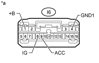
Text in Illustration *a Front view of wire harness connector
(to Parking Assist ECU)
Disconnect the parking assist ECU connector.
-
Measure the resistance according to the value(s) in the table below.
Standard Resistance Tester Connection Condition Specified Condition I6-4 (GND1) - Body ground Always Below 1 Ω -
Measure the voltage according to the value(s) in the table below.
Standard Voltage Tester Connection Condition Specified Condition I6-1 (+B) - I6-4 (GND1) Always 11 to 14 V I6-8 (IG) - I6-4 (GND1) Ignition switch ON 11 to 14 V I6-9 (ACC) - I6-4 (GND1) Ignition switch ACC 11 to 14 V
NG 
REPAIR OR REPLACE HARNESS OR CONNECTOR
OK 
-
-
INSPECT RADIO AND DISPLAY RECEIVER ASSEMBLY
-
Remove the radio and display receiver assembly Click here.
-
Measure the resistance according to the value(s) in the table below.
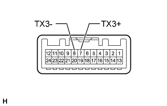
Standard Resistance Tester Connection Condition Specified Condition 7 (TX3+) - 8 (TX3-) Always 60 to 80 Ω
NG
REPLACE RADIO AND DISPLAY RECEIVER ASSEMBLY Click here
OK
-
-
CHECK HARNESS AND CONNECTOR (RADIO AND DISPLAY RECEIVER ASSEMBLY - PARKING ASSIST ECU)
-
Disconnect the H50 radio and display receiver assembly connector.
-
Disconnect the I6 parking assist ECU connector.
-
Measure the resistance according to the value(s) in the table below.
Standard Resistance Tester Connection Condition Specified Condition H50-7 (TX3+) - I6-11 (TX+) Always Below 1 Ω H50-8 (TX3-) - I6-10 (TX-) Always Below 1 Ω H50-7 (TX3+) - Body ground Always 10 kΩ or higher H50-8 (TX3-) - Body ground Always 10 kΩ or higher
NG
REPAIR OR REPLACE HARNESS OR CONNECTOR
OK
-
-
CHECK PARKING ASSIST ECU
-
Replace the parking assist ECU with a known good one.
-
for LHD: Click here
-
for RHD: Click here
-
-
Clear the DTCs Click here.
-
Check for DTCs Click here.
OK No DTCs are output.
NG
REPLACE RADIO AND DISPLAY RECEIVER ASSEMBLY Click here
OK
END (PARKING ASSIST ECU IS DEFECTIVE)
-