ANTI-LOCK BRAKE SYSTEM, Diagnostic DTC:C1243, C1245, C1279

| DTC Code | DTC Name |
|---|---|
| C1243 | Acceleration Sensor Stuck Malfunction |
| C1245 | Acceleration Sensor Output Malfunction |
| C1279 | Acceleration Sensor Output Voltage Malfunction (Test Mode DTC) |
DESCRIPTION
The skid control ECU receives signals from the acceleration sensor via the CAN communication system.
The acceleration sensor detects the vehicle's condition using 2 circuits (GL1, GL2).
If there is trouble in the bus lines between the acceleration sensor and the CAN communication system, DTC U0124 (malfunction in CAN communication with the acceleration sensor) are stored.
These DTCs are also stored when calibration has not been completed.
DTC C1279 can be cleared when the acceleration sensor sends an acceleration signal or test mode ends. DTC C1279 is stored only in test mode.
| DTC Code | DTC Detection Condition | Trouble Area |
|---|---|---|
| C1243 | While the vehicle speed changes from 30 km/h (19 mph) to 0 km/h (0 mph), the condition that the values of GL1 and GL2 do not change by 0.0294 G or more occurs 16 times or more. |
|
| C1245 | At a vehicle speed of 30 km/h (19 mph) or more, the difference between the forward and backward G calculated from the acceleration sensor value and that calculated from the vehicle speed exceeds 0.35 G for 60 seconds or more. | |
| C1279 | Stored only during test mode. |
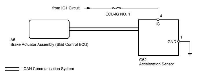
WIRING DIAGRAM
INSPECTION PROCEDURE
Note
-
When replacing the acceleration sensor, perform calibration Click here.
-
Inspect the fuses for circuits related to this system before performing the following inspection procedure.
Tech Tips
When DTC U0124 is output together with DTC C1243 and/or C1245, inspect and repair the trouble areas indicated by DTC U0124 first Click here.
PROCEDURE
-
CHECK DTC
-
Clear the DTCs Click here.
-
Turn the ignition switch off.
-
At a speed of 30 km/h (19 mph) or more, drive the vehicle, turn the steering wheel and decelerate (depress the brake pedal) the vehicle.
-
Turn the ignition switch to ON again and check that no CAN communication system DTC is output Click here.
Result Result Proceed to DTC output (relating to acceleration sensor) A DTC output (relating to CAN communication system) for LHD without Entry and Start System B DTC output (relating to CAN communication system) for RHD without Entry and Start System C
B 
GO TO CAN COMMUNICATION SYSTEM (HOW TO PROCEED WITH TROUBLESHOOTING) Click here
C
GO TO CAN COMMUNICATION SYSTEM (HOW TO PROCEED WITH TROUBLESHOOTING) Click here
A 
-
-
CHECK ACCELERATION SENSOR
-
Turn the ignition switch off.
-
Check that the acceleration sensor is installed properly Click here.
OK The sensor is tightened to the specified torque. The sensor is not tilted.
NG
INSTALL ACCELERATION SENSOR CORRECTLY Click here
OK
-
-
CHECK TERMINAL VOLTAGE (IG, GND)
-
Disconnect the G52 acceleration sensor connector.
-
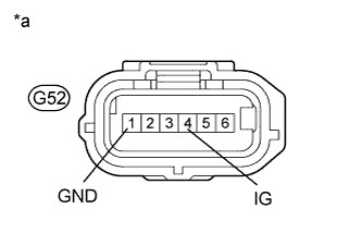
Text in Illustration *a Front view of wire harness connector
(to Acceleration Sensor)
Measure the voltage according to the value(s) in the table below.
Standard Voltage Tester Connection Switch Condition Specified Condition G52-4 (IG) - Body ground Ignition switch ON 11 to 14 V -
Measure the resistance according to the value(s) in the table below.
Standard Resistance Tester Connection Condition Specified Condition G52-1 (GND) - Body ground Always Below 1 Ω Result Result Proceed to OK (When troubleshooting in accordance with diagnostic trouble code chart) A OK (When troubleshooting in accordance with problem symptoms table) B NG C
B
PROCEED TO NEXT SUSPECTED AREA SHOWN IN PROBLEM SYMPTOMS TABLE Click here
C
REPAIR OR REPLACE HARNESS OR CONNECTOR
A 
REPLACE ACCELERATION SENSOR Click here
-