LUMBAR SUPPORT ADJUSTER ASSEMBLY REMOVAL

-
REMOVE FRONT SEAT HEADREST ASSEMBLY
-
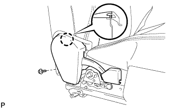
REMOVE FRONT OUTER SEAT TRACK BRACKET COVER
-
Operate the power seat switch knob and move the seat to the rearmost position.
-
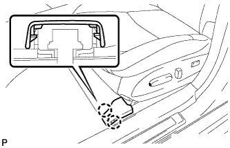
Disengage the 2 claws and remove the front outer seat track bracket cover.
-
-
REMOVE FRONT INNER SEAT TRACK BRACKET COVER
-
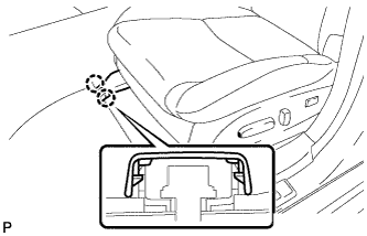
Disengage the 2 claws and remove the front inner seat track bracket cover.
-
-
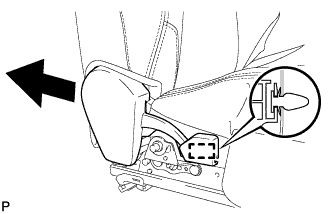
REMOVE REAR OUTER SEAT TRACK BRACKET COVER
-
Operate the power seat switch knob and move the seat to the foremost position.
-
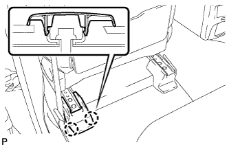
Disengage the 2 claws and remove the rear outer seat track bracket cover.
-
-
REMOVE REAR INNER SEAT TRACK BRACKET COVER
-
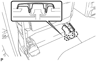
Disengage the 2 claws and remove the rear inner seat track bracket cover.
-
-
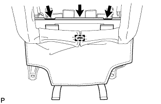
REMOVE FRONT SEAT ASSEMBLY
-
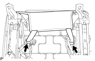
Operate the power seat switch knob and move the seat to the foremost position.
-
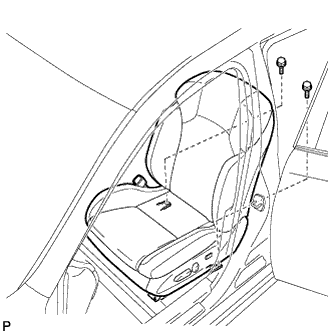
Remove the 2 bolts on the rear side of the seat.
-
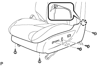
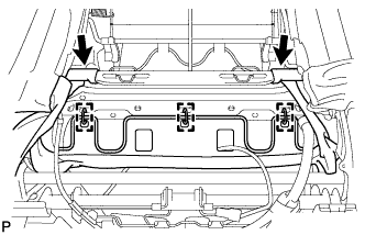
Operate the power seat switch knob and move the seat to the rearmost position.
-
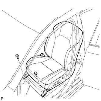
Remove the 2 bolts on the front side of the seat.
-
Operate the power seat switch knob and move the seat to the center position. Also, operate the power seat switch knob and move the seatback to the upright position.
-
Disconnect the cable from the negative (-) battery terminal.
CAUTION:
Wait at least 90 seconds after disconnecting the cable from the negative (-) battery terminal to disable the SRS system Click here.
Note
When disconnecting the cable, some systems need to be initialized after the cable is reconnected Click here.
-
Disconnect the connectors under the seat.
-
Remove the front seat assembly.
Note
Be careful not to damage the vehicle body.
-
-
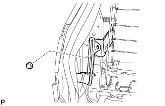
REMOVE FRONT SEAT INNER BELT ASSEMBLY
-
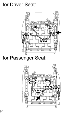
for Driver Seat:
-
Disconnect the connector and disengage the 3 clamps.
-
-
for Passenger Seat:
-
Disconnect the connector and disengage the 4 clamps.
-
-
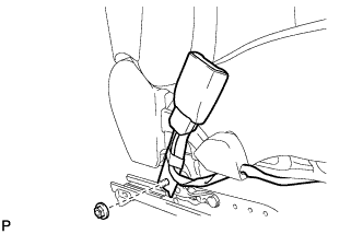
Remove the nut and front seat inner belt assembly.
-
-
REMOVE RECLINING POWER SEAT SWITCH KNOB
-
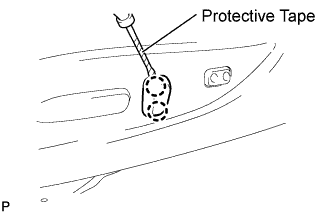
Using a screwdriver wrapped with protective tape, disengage the 2 claws and remove the reclining power seat switch knob.
-
-
REMOVE SLIDE AND VERTICAL POWER SEAT SWITCH KNOB
-
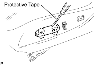
Using a screwdriver wrapped with protective tape, disengage the 4 claws and remove the slide and vertical power seat switch knob.
-
-
REMOVE FRONT SEAT CUSHION SHIELD ASSEMBLY
-
Disengage the 2 hooks and remove the 2 rubber bands of the front seatback board from the front seat frame.
-
Remove the 6 screws.
-
Disengage the claw and remove the front seat cushion shield assembly.
-
Disconnect the connector from the front power seat lumbar switch.
-
-
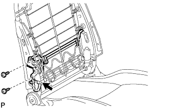
REMOVE FRONT SEAT CUSHION INNER SHIELD
-
Remove the screw.
-
Disengage the claw.
-
Separate the guide and remove the front seat cushion inner shield as shown in the illustration.
-
-
REMOVE FRONT SEATBACK BOARD SUB-ASSEMBLY
-
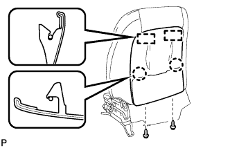
Open the lower part of the seatback board. Then remove the 2 screws.
-
Disengage the 2 claws.
-
Disengage the 2 hooks and remove the front seatback board sub-assembly.
-
-
REMOVE FRONT SEAT HEADREST SUPPORT
-
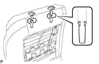
Disengage the 4 claws and remove the 2 headrest supports.
-
-
REMOVE FRONT SEATBACK BOARD COVER SUB-ASSEMBLY
-
Remove the hog ring.
-
Disengage the hooks and remove the front seatback board cover sub-assembly.
-
-
REMOVE FRONT SEATBACK COVER WITH PAD
-

Remove the 10 hog rings.
-
Disengage the 2 hooks.
-
Remove the 3 hog rings.
-
Remove the nut and the seatback cover bracket.
-
Remove the front seatback cover with pad from the seatback frame.
-
-
REMOVE LUMBAR SUPPORT ADJUSTER ASSEMBLY
-
Disconnect the connector.
-
Remove the 2 screws and the lumbar support adjuster assembly.
-