CENTER AIRBAG SENSOR ASSEMBLY INSTALLATION

-
INSTALL CENTER AIRBAG SENSOR ASSEMBLY
-
Check that the engine switch is off.
-
Check that the cable is disconnected from the negative (-) battery terminal.
CAUTION:
Wait at least 90 seconds after disconnecting the cable from the negative (-) battery terminal to disable the SRS system.
-
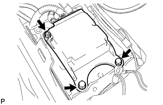
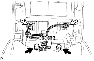
Install the center airbag sensor assembly with the 2 bolts and nut.
- Torque:
- 18 N*m { 184 kgf*cm, 13 ft.*lbf }
Note
-
If the center airbag sensor assembly has been dropped, or there are any cracks, dents or other defects in the case or connector, replace it with a new one.
-
When installing the center airbag sensor assembly, be careful that the SRS wiring does not interfere with other parts and that it is not pinched between other parts.
-
When the engine switch is first turned on (IG) after the center airbag sensor assembly has been replaced, make sure that no one is in the vehicle.
-
Connect the holder (with connectors).
Note
When connecting the airbag connector, take care not to damage the airbag wire harness.
-
Check that the waterproof sheet is properly set.
-
Check that there is no looseness in the installation parts of the center airbag sensor assembly.
-
-
INSTALL CONSOLE BOX
-
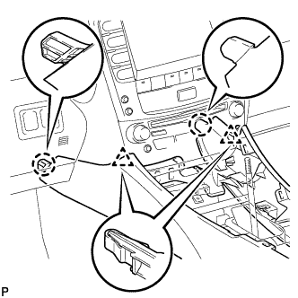
Engage the 2 claws and 2 clips.
-
Install the 2 bolts.
-
Install the 2 bolts.
-
Connect the connector.
-
Connect the 2 connectors.
-
Engage the 2 clamps.
-
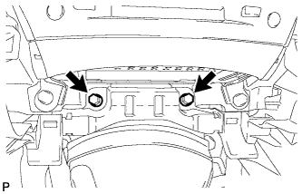
Install the 2 bolts.
-
-
INSTALL CONSOLE BOX REGISTER ASSEMBLY
-
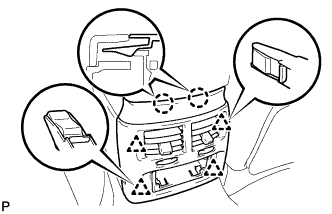
Engage the 2 claws and 4 clips, and then install the console box register assembly.
-
-
INSTALL REAR ASH RECEPTACLE ASSEMBLY
-
Install the rear ash receptacle assembly.
-
-
INSTALL FRONT ASH RECEPTACLE ASSEMBLY
-
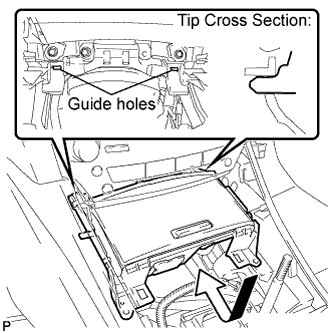
Connect the connectors.
-
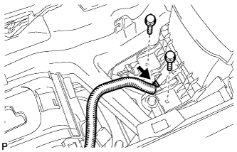
Insert the protruding parts of the front ash receptacle assembly into the 2 guide holes as shown in the illustration.
-
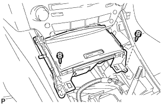
Install the front ash receptacle assembly with the 2 screws <E>.
-
-
INSTALL CONSOLE PANEL SUB-ASSEMBLY
-
Connect the connectors.
-
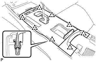
Engage the 8 clips to install the console panel sub-assembly.
-
-
INSTALL UPPER NO. 2 CONSOLE PANEL GARNISH
-
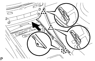
Engage the claw and 2 clips to install the upper No. 2 console panel garnish.
-
-
INSTALL UPPER NO. 1 CONSOLE PANEL GARNISH
-
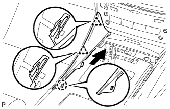
Engage the claw and 2 clips to install the upper No. 1 console panel garnish.
-
-
INSTALL SHIFT LEVER KNOB SUB-ASSEMBLY
-
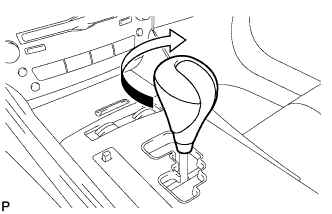
Turn the shift lever knob clockwise and install the shift lever knob sub-assembly.
-
-
CONNECT CABLE TO NEGATIVE BATTERY TERMINAL
Note
When disconnecting the cable, some systems need to be initialized after the cable is reconnected Click here.
-
INSPECT SRS WARNING LIGHT
-
Inspect the SRS warning light Click here.
-