NETWORK GATEWAY ECU INSTALLATION

-
INSTALL NETWORK GATEWAY ECU
-
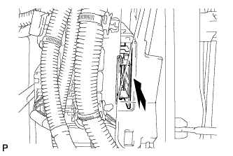
Install the network gateway ECU.
-
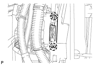
Engage the 2 claws to install the cover.
-
Connect the connector.
-
-
INSTALL GLOVE COMPARTMENT DOOR ASSEMBLY (for LHD)
-
Connect the connectors.
-
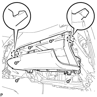
Engage the 2 claws.
-
Install the glove compartment door assembly with the 5 screws <D>.
-
-
INSTALL FRONT PASSENGER SIDE KNEE AIRBAG ASSEMBLY (for LHD)
-
Check that the engine switch is off.
-
Check that the battery negative (-) cable is disconnected.
CAUTION:
Wait at least 90 seconds after disconnecting the cable from the negative (-) battery terminal to disable the SRS system.
-
Connect the front passenger side knee airbag connector to the front passenger side knee airbag assembly.
Note
When connecting the airbag connector, take care not to damage the airbag wire harness.
-
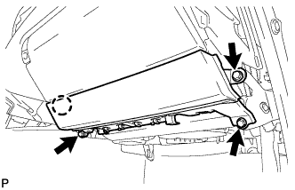
Install the front passenger side knee airbag assembly with the 3 bolts and claw.
- Torque:
- 10 N*m { 102 kgf*cm, 7 ft.*lbf }
-
-
INSTALL NO. 2 INSTRUMENT PANEL UNDER COVER SUB-ASSEMBLY (for LHD)
-
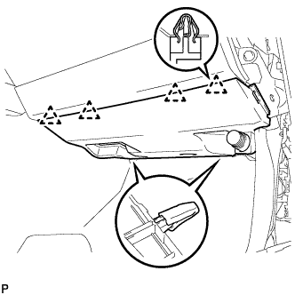
Engage the 4 clips and install the No. 2 instrument panel under cover sub-assembly.
-
-
INSTALL LOWER INSTRUMENT PANEL FINISH PANEL SUB-ASSEMBLY (for RHD)
-
Connect the connectors.
-
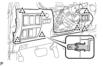
Engage the 7 clips and install the lower instrument panel finish panel sub-assembly.
-
-
INSTALL NO. 1 INSTRUMENT PANEL UNDER COVER SUB-ASSEMBLY (for RHD)
-
Connect the connectors.
-
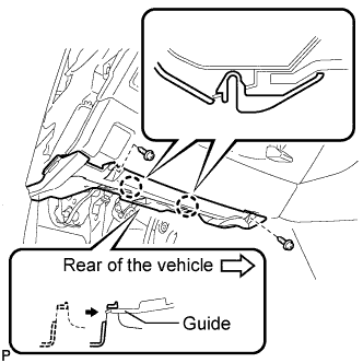
Insert the No. 1 instrument panel under cover sub-assembly into the guide as shown in the illustration.
-
Engage the 2 claws.
-
Install the No. 1 instrument panel under cover sub-assembly with the 2 screws <D>.
-
-
INSTALL SIDE INSTRUMENT PANEL
-
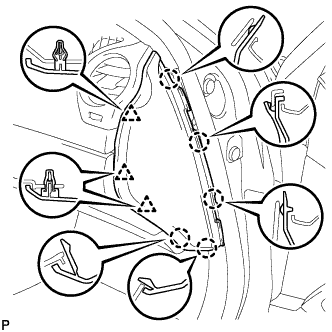
Engage the 5 claws and 3 clips, and then install the side instrument panel RH.
-
-
INSTALL FRONT DOOR OPENING TRIM COVER
-
INSTALL FRONT DOOR SCUFF PLATE
-
CONNECT CABLE TO NEGATIVE BATTERY TERMINAL
-
INSPECT SRS WARNING LIGHT
Note
Some systems need initialization when disconnecting the cable from the negative battery terminal Click here.