STEERING GEAR INSTALLATION

-
INSTALL POWER STEERING LINK ASSEMBLY (for LHD)
-
Install the power steering link assembly with the 2 bolts, 2 washers and 2 nuts.
- Torque:
- 118 N*m { 1203 kgf*cm, 87 ft.*lbf }
-
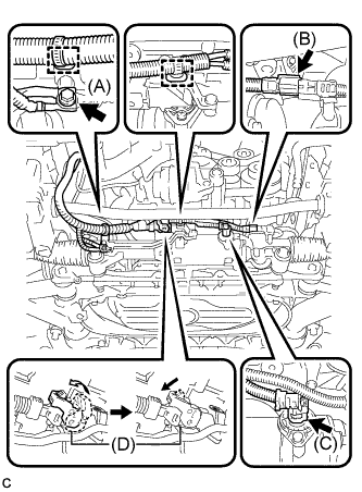
Connect the wire harness connector (D) to the power steering link assembly and securely lock the connector.
-
Connect the 2 wire harness connectors (B) and (C) to the power steering link assembly.
-
Install the 2 wire harness clamps to the power steering link assembly.
-
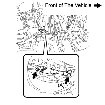
Connect the earth wire to the bracket with the bolt (A).
- Torque:
- 8.0 N*m { 82 kgf*cm, 71 in.*lbf }
-
-
INSTALL POWER STEERING LINK ASSEMBLY (for RHD)
-
Install the power steering link assembly with the 2 bolts, 2 washers, and 2 nuts.
- Torque:
- 118 N*m { 1203 kgf*cm, 87 ft.*lbf }
-
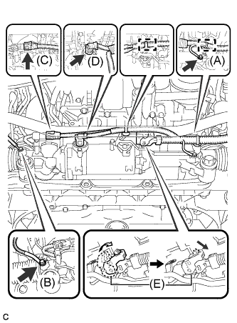
Connect the wire harness connector (E) to the power steering link assembly and securely lock the connector.
-
Connect the 2 wire harness connectors (C) and (D) to the power steering link assembly.
-
Install the 2 wire harness clamps to the power steering link assembly.
-
Connect the earth wire with the 2 bolts (A) and (B).
- Torque:
- Bolt (A)
- 13 N*m { 133 kgf*cm, 10 ft.*lbf }
- Bolt (B)
- 5.0 N*m { 51 kgf*cm, 44 in.*lbf }
-
-
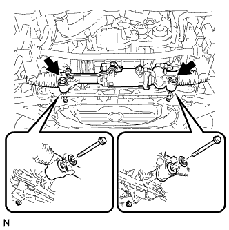
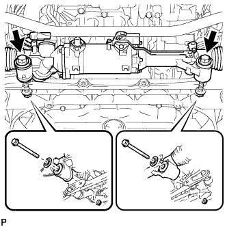
CONNECT TIE ROD END LH
-
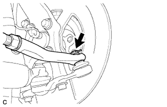
Connect the tie rod end LH to the steering knuckle with the nut.
- Torque:
- 65 N*m { 663 kgf*cm, 48 ft.*lbf }
-
Install a new clip.
Note
If the holes for the clip are not aligned, tighten the nut up to 60° further.
-
-
CONNECT TIE ROD END RH
Tech Tips
Perform the same procedure as the LH side.
-
CONNECT STEERING SLIDING YOKE SUB-ASSEMBLY
-
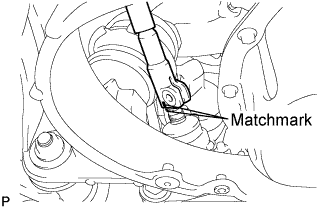
Align the matchmarks on the steering sliding yoke sub-assembly and the power steering link assembly.
-
Install the bolt (A) and tighten the 2 bolts.
- Torque:
- 35 N*m { 360 kgf*cm, 26 ft.*lbf }
-
-
INSTALL FRONT LOWER SUSPENSION MEMBER PROTECTOR
-
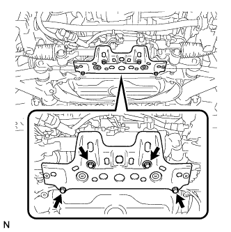
Install the front lower suspension member protector to the front suspension cross member with the 4 bolts.
- Torque:
- 8.0 N*m { 82 kgf*cm, 71 in.*lbf }
-
-
INSTALL NO. 2 ENGINE UNDER COVER
-
INSTALL ENGINE UNDER COVER
-
INSTALL FRONT WHEELS
- Torque:
- 103 N*m { 1050 kgf*cm, 76 ft.*lbf }
-
STABILIZE SUSPENSION
-
Install the rear wheels.
-
Lower the vehicle to the ground.
-
Bounce the vehicle up and down at the corners to stabilize the rear suspension.
-
Remove the rear wheels.
-
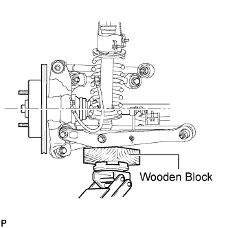
Jack up the axle carrier, with a wooden block placed between the jack and axle carrier, to apply a load to the suspension so that the rear drive shaft assembly becomes level.
-
-
PLACE FRONT WHEELS FACING STRAIGHT AHEAD
-
CONNECT CABLE TO NEGATIVE BATTERY TERMINAL
Note
-
Make sure that the cable has been disconnected from the battery terminal for at least 2 seconds before reconnecting the cable.
-
Connect the cable to the negative (-) battery terminal with the front wheels facing straight ahead.
-
When disconnecting the cable, some systems need to be initialized after the cable is reconnected Click here.
-
-
INSPECT AND ADJUST FRONT WHEEL ALIGNMENT
Tech Tips
-
INITIALIZE ROTATION ANGLE SENSOR AND CALIBRATE TORQUE SENSOR ZERO POINT
Tech Tips