STEERING GEAR REMOVAL

-
PLACE FRONT WHEELS FACING STRAIGHT AHEAD
-
SECURE STEERING WHEEL
-
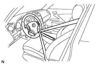
Secure the steering wheel with the seat belt in order to prevent rotation.
Tech Tips
This operation is useful to prevent damage to the spiral cable.
-
-
DISCONNECT CABLE FROM NEGATIVE BATTERY TERMINAL
CAUTION:
Wait at least 90 seconds after disconnecting the cable from the negative (-) battery terminal to disable the SRS system.
Note
When disconnecting the cable, some systems need to be initialized after the cable is reconnected Click here.
-
REMOVE FRONT WHEELS
-
REMOVE ENGINE UNDER COVER
-
REMOVE NO. 2 ENGINE UNDER COVER
-
REMOVE FRONT LOWER SUSPENSION MEMBER PROTECTOR
-
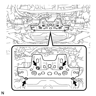
Remove the 4 bolts and the front lower suspension member protector.
-
-
SEPARATE STEERING SLIDING YOKE SUB-ASSEMBLY
-
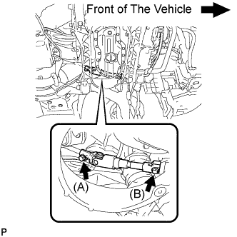
Loosen the bolt (A) and remove the bolt (B), then slide the steering sliding yoke sub-assembly.
Note
-
Do not remove the bolt (A).
-
Do not separate the steering sliding yoke sub-assembly from the power steering gear assembly.
-
-
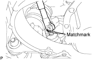
Put matchmarks on the steering sliding yoke sub-assembly and the power steering link assembly.
-
Separate the steering sliding yoke sub-assembly from the power steering link assembly.
-
-
SEPARATE TIE ROD END LH
-
Remove the clip and the nut.
-
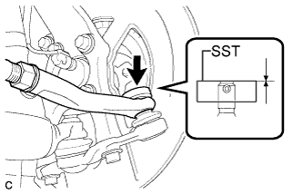
Install SST to the tie rod end.
- SST
- 09960-20010 ( 09961-02060 )
Note
Make sure that the upper ends of the tie rod end and SST are aligned.
-
Using SST, separate the tie rod end from the steering knuckle.
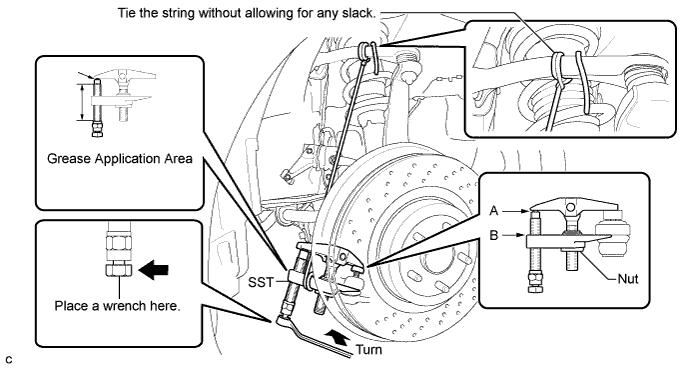
- SST
- 09960-20010 ( 09961-02010 )
CAUTION:
Apply grease to the bolt threads and the tip of SST.
Note
-
Be sure to tighten the string firmly to secure SST to the steering knuckle to prevent SST from falling off.
-
Install SST with the center nut so that A and B are parallel. Otherwise, the dust cover may be damaged.
-
Be sure to place a wrench on the part indicated in the illustration.
-
Do not damage the front disc brake dust cover.
-
Do not damage the ball joint dust cover.
-
Do not damage the steering knuckle.
-
-
SEPARATE TIE ROD END RH
Tech Tips
Perform the same procedure as the LH side.
-
REMOVE POWER STEERING LINK ASSEMBLY (for LHD)
-
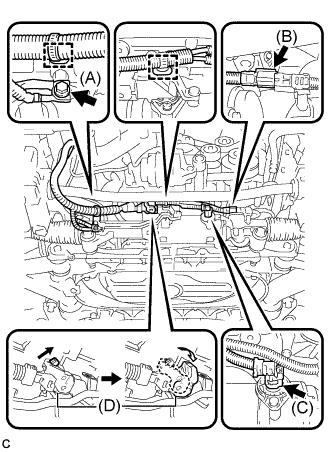
Remove the bolt (A) to disconnect the earth wire from the bracket.
-
Remove the 2 clamps to disconnect the wire harness from the bracket.
-
Disconnect the 2 connectors (B) and (C) from the power steering link assembly.
-
Release the lock of the connector (D) and disconnect the connector (D) from the power steering link assembly.
-
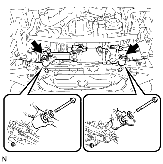
Remove the 2 bolts, 2 washers, 2 nuts, and the power steering link assembly from the front suspension cross member.
-
-
REMOVE POWER STEERING LINK ASSEMBLY (for RHD)
-
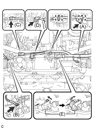
Remove the 2 bolts (A) and (B) to disconnect the earth wire.
-
Remove the 2 clamps to disconnect the wire harness from the bracket.
-
Disconnect the 2 connectors (C) and (D) from the power steering link assembly.
-
Release the lock of the connector (E) and disconnect the connector (E) from the power steering link assembly.
-
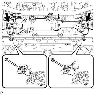
Remove the 2 bolts, 2 washers, 2 nuts, and the power steering link assembly from the front suspension cross member.
-