STEERING COLUMN ASSEMBLY INSTALLATION

-
INSTALL NO. 2 STEERING INTERMEDIATE SHAFT ASSEMBLY
-
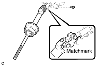
Align the matchmarks on the No. 2 steering intermediate shaft assembly and the steering column assembly.
-
Install the bolt.
- Torque:
- 35 N*m { 360 kgf*cm, 26 ft.*lbf }
-
-
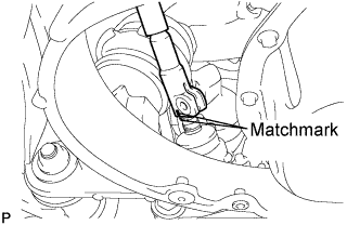
INSTALL STEERING SLIDING YOKE SUB-ASSEMBLY
-
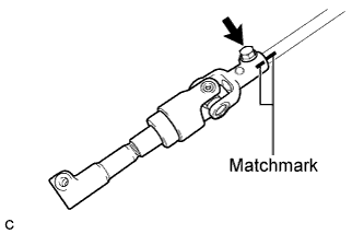
Align the matchmarks on the steering sliding yoke sub-assembly and the No. 2 steering intermediate shaft assembly.
-
Temporarily install the bolt.
Tech Tips
Torque the bolt after connecting the steering sliding yoke sub-assembly to the power steering link assembly.
-
-
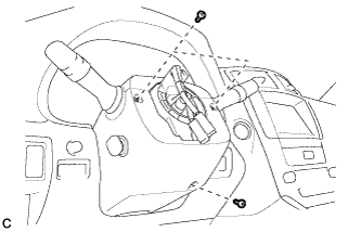
INSTALL STEERING COLUMN ASSEMBLY
-
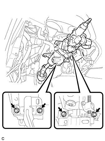
Install the steering column assembly with the 4 nuts.
- Torque:
- 26 N*m { 260 kgf*cm, 19 ft.*lbf }
-
Connect the connectors and wire harness clamps to the steering column assembly.
-
Install the clamp to the steering column hole shield.
-
-
INSTALL BRAKE PEDAL RETURN SPRING
-
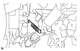
Install the brake pedal return spring.
-
-
INSTALL NO. 1 AIR DUCT
-
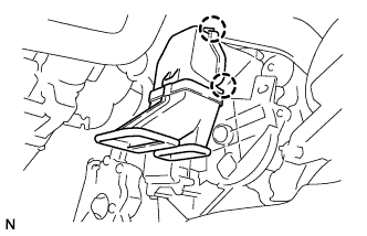
Engage the 2 claws to install the No. 1 air duct.
-
-
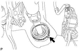
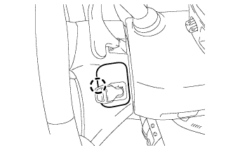
CONNECT STEERING SLIDING YOKE SUB-ASSEMBLY
-
Align the matchmarks on the steering sliding yoke sub-assembly and the power steering link assembly.
-
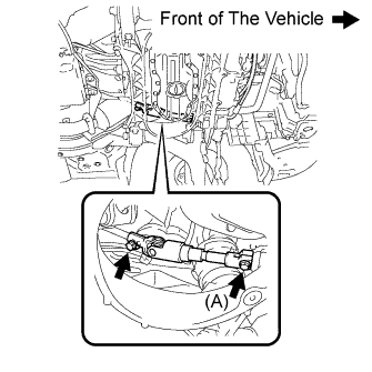
Install the bolt (A) and tighten the 2 bolts.
- Torque:
- 35 N*m { 360 kgf*cm, 26 ft.*lbf }
-
-
INSTALL DRIVER SIDE KNEE AIRBAG ASSEMBLY
Tech Tips
Refer to the instructions for Installation of the driver side knee airbag assembly Click here.
-
PLACE FRONT WHEELS FACING STRAIGHT AHEAD
-
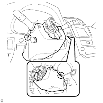
INSTALL TURN SIGNAL SWITCH ASSEMBLY WITH SPIRAL CABLE SUB-ASSEMBLY
-
Install the turn signal switch assembly with spiral cable sub-assembly to the steering column assembly with the clamp.
-
Connect the connectors to the turn signal switch assembly with spiral cable sub-assembly.
-
-
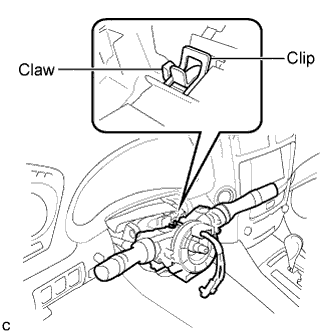
INSTALL TILT AND TELESCOPIC SWITCH
-
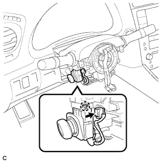
Engage the claw to install the tilt and telescopic switch.
-
Connect the connector.
-
-
INSTALL STEERING COLUMN COVER
-
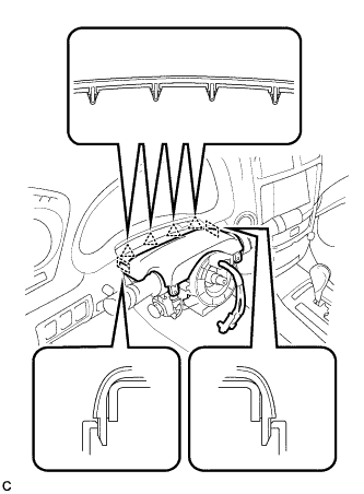
Engage the 4 clips and 2 guides to install the upper steering column cover onto the instrument panel cluster finish panel.
-
Engage the claw to install the upper steering column cover.
-
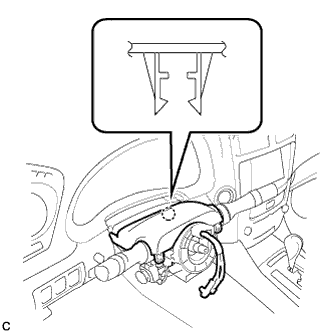
Engage the 2 claws to install the lower steering column cover.
Note
Do not damage the tilt and telescopic switch.
-
Install the 3 screws.
- Torque:
- 2.0 N*m { 20 kgf*cm, 18 in.*lbf }
-
-
ADJUST SPIRAL CABLE
-
Check that the engine switch is off.
-
Check that the battery negative (-) cable is disconnected.
CAUTION:
Wait at least 90 seconds after disconnecting the cable from the negative (-) battery terminal to disable the SRS system.
-
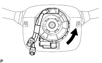
Rotate the spiral cable counterclockwise slowly by hand until it stops.
Note
Do not turn the spiral cable using the airbag wire harness.
-
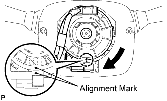
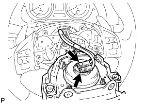
Rotate the spiral cable clockwise approximately 2.5 turns to align the marks.
Note
Do not turn the spiral cable using the airbag wire harness.
Tech Tips
The spiral cable will rotate approximately 2.5 turns to both the left and right from the center.
-
-
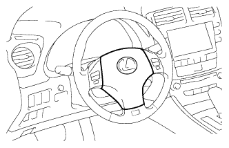
INSTALL STEERING WHEEL ASSEMBLY
-
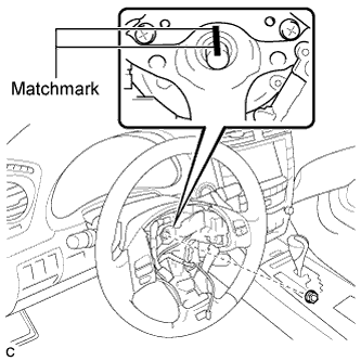
Align the matchmarks on the steering wheel assembly and steering main shaft.
-
Install the steering wheel assembly set nut.
- Torque:
- 50 N*m { 510 kgf*cm, 37 ft.*lbf }
-
Connect the connectors to the spiral cable sub-assembly.
-
-
INSPECT STEERING WHEEL CENTER POINT
-
INSTALL STEERING PAD
-
Check that the engine switch is off.
-
Check that the cable is disconnected from the negative (-) battery terminal.
CAUTION:
Wait at least 90 seconds after disconnecting the cable from the negative (-) battery terminal to disable the SRS system.
-
Connect the 2 airbag connectors to the steering pad.
Note
When connecting the airbag connector, take care not to damage the airbag wire harness.
-
Connect the horn connector to the steering pad.
-
Confirm that the circumference groove of the "TORX" screw fits in the screw case, and place the steering pad onto the steering wheel assembly.
-
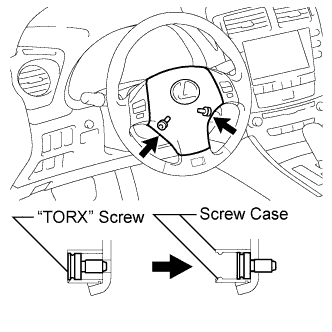
Using a "TORX" socket wrench (T30), tighten the 2 "TORX" screws.
- Torque:
- 8.8 N*m { 90 kgf*cm, 78 in.*lbf }
-
-
INSTALL LOWER NO. 3 STEERING WHEEL COVER
-
Install the lower No. 3 steering wheel cover with the claw.
-
-
INSTALL LOWER NO. 2 STEERING WHEEL COVER
-
Install the lower No. 2 steering wheel cover with the claw.
-
-
CONNECT CABLE TO NEGATIVE BATTERY TERMINAL
Note
-
When disconnecting the cable, some systems need to be initialized after the cable is reconnected Click here.
-
Reset the auto tilt away function setting to the previous condition by changing the customize parameter Click here.
-
-
INSPECT STEERING PAD
-
With the steering pad installed on the vehicle, perform a visual check. If there are any following defects, replace the steering pad with a new one:
-
Cuts, minute cracks or marked discoloration on the steering pad top surface or grooves.
-
-
Make sure that the horn sounds.
Tech Tips
If the horn does not sound, inspect the horn system Click here.
-
-
REGISTER ECU CODE
Note
When replacing the steering lock actuator assembly, perform initialization.
-
INSPECT SRS WARNING LIGHT