PARKING BRAKE SWITCH INSTALLATION

-
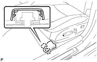
INSTALL PARKING BRAKE SWITCH ASSEMBLY (for LHD)
-
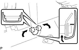
Install the parking brake switch assembly to the parking brake control pedal assembly with the screw.
- Torque:
- 0.9 N*m { 9 kgf*cm, 8 in.*lbf }
-
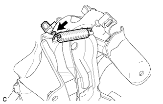
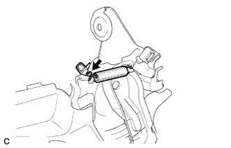
Install the tension spring to the parking brake control pedal assembly.
-
-
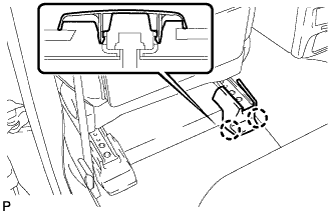
INSTALL PARKING BRAKE CONTROL PEDAL ASSEMBLY (for LHD)
-
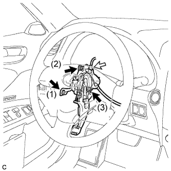
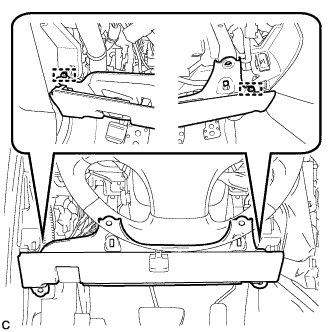
Install the parking brake control pedal assembly and temporarily tighten the 3 nuts.
-
Fully tighten the 3 nuts in the order shown in the illustration.
- Torque:
- 13 N*m { 133 kgf*cm, 10 ft.*lbf }
-
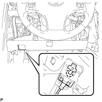
Connect the parking brake switch connector.
-
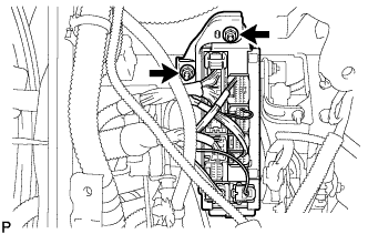
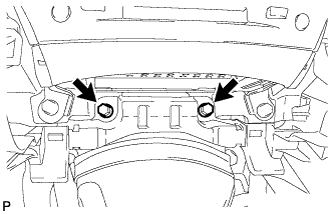
Install the instrument panel junction block assembly with the 2 nuts.
-
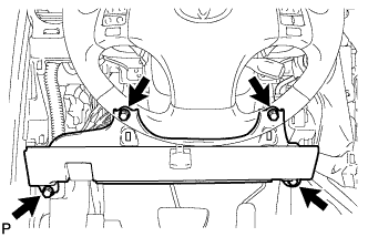
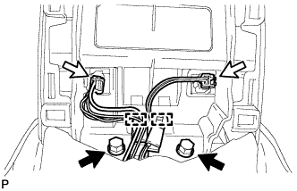
Install the parking brake control pedal assembly to the body with the 3 nuts.
- Torque:
- 6.0 N*m { 61 kgf*cm, 53 in.*lbf }
-
-
INSTALL PARKING BRAKE SWITCH ASSEMBLY (for RHD)
-
Install the parking brake switch assembly to the parking brake control pedal assembly with the screw.
- Torque:
- 0.9 N*m { 9 kgf*cm, 8 in.*lbf }
-
Install the tension spring to the parking brake control pedal assembly.
-
-
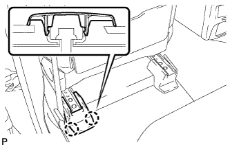
INSTALL PARKING BRAKE CONTROL PEDAL ASSEMBLY (for RHD)
-
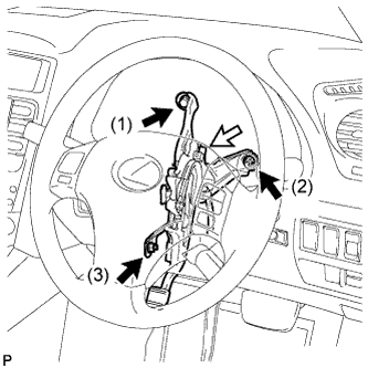
Install the parking brake control pedal assembly to the body and temporarily tighten the bolt and 2 nuts.
-
Fully tighten the bolt and 2 nuts in the order shown in the illustration.
- Torque:
- 13 N*m { 133 kgf*cm, 10 ft.*lbf }
-
Connect the parking brake switch connector.
-
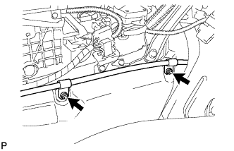
Install the parking brake control pedal assembly with the 2 nuts.
- Torque:
- 6.0 N*m { 61 kgf*cm, 53 in.*lbf }
-
-
INSTALL NO. 1 AIR DUCT (for RHD)
-
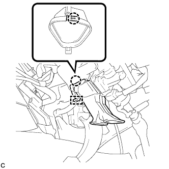
Engage the claw and guide, and install the No. 1 air duct.
-
-
INSTALL NO. 2 REAR AIR DUCT (for LHD)
-
INSTALL NO. 1 REAR AIR DUCT (for RHD)
-
INSTALL REAR AIR DUCT GUIDE LH (for LHD)
-
INSTALL REAR AIR DUCT GUIDE RH (for RHD)
-
INSTALL FRONT FLOOR SILENCER PAD LH (for LHD)
-
INSTALL FRONT FLOOR SILENCER PAD RH (for RHD)
-
INSTALL NO. 3 DASH PANEL INSULATOR PAD
-
INSTALL FRONT FLOOR FOOTREST LH (for LHD)
-
INSTALL FRONT FLOOR FOOTREST RH (for RHD)
-
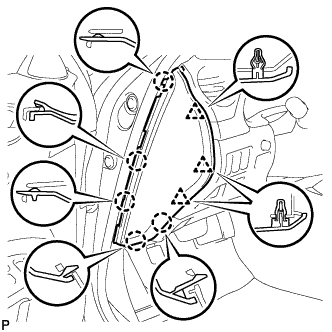
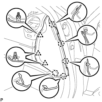
INSTALL LOWER CENTER PILLAR GARNISH LH (for LHD)
-
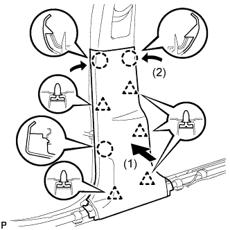
Engage the 5 clips and 3 claws, and install the lower center pillar garnish LH.
-
-
INSTALL FRONT SEAT OUTER BELT ASSEMBLY LH (for LHD)
-
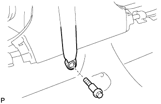
Install the front seat outer belt assembly LH with the bolt.
- Torque:
- 42 N*m { 428 kgf*cm, 31 ft.*lbf }
-
-
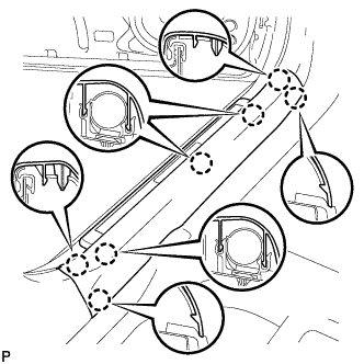
INSTALL REAR DOOR SCUFF PLATE LH (for LHD)
-
Engage the 2 clips.
-
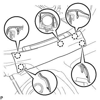
Engage the 5 claws and install the rear door scuff plate LH.
-
-
INSTALL LOWER CENTER PILLAR GARNISH RH (for RHD)
Tech Tips
Use the same procedure for the RH side and the LH side.
-
INSTALL FRONT SEAT OUTER BELT ASSEMBLY RH (for RHD)
Tech Tips
Use the same procedure for the RH side and the LH side.
-
INSTALL REAR DOOR SCUFF PLATE RH (for RHD)
Tech Tips
Use the same procedure for the RH side and the LH side.
-
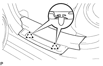
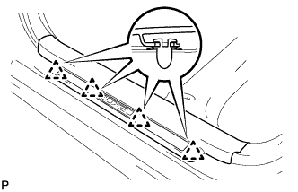
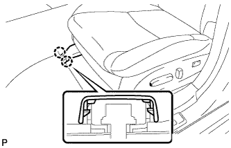
INSTALL LAP BELT OUTER ANCHOR COVER
-
Engage the 2 claws and install the lap belt outer anchor cover as shown in the illustration.
Tech Tips
Use the same procedure to install the cover on the other side.
-
-
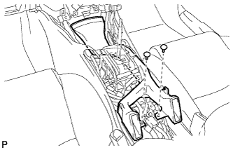
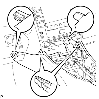
INSTALL DRIVER SIDE KNEE AIRBAG ASSEMBLY
-
Check that the engine switch is off.
-
Check that the battery negative (-) cable is disconnected.
CAUTION:
Wait at least 90 seconds after disconnecting the cable from the negative (-) battery terminal to disable the SRS system.
-
Connect the driver side knee airbag connector to the driver side knee airbag assembly.
Note
When connecting the airbag connector, take care not to damage the airbag wire harness.
-
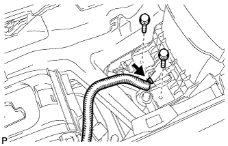
Temporarily install the driver side knee airbag assembly with the 2 pins.
-
Install the driver side knee airbag assembly with the 4 bolts.
- Torque:
- 10 N*m { 102 kgf*cm, 7 ft.*lbf }
-
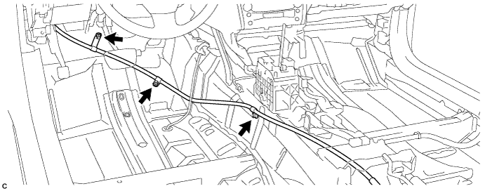
Install the hood lock control cable with the claw.
-
-
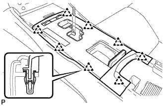
INSTALL LOWER INSTRUMENT PANEL FINISH PANEL SUB-ASSEMBLY
-
Connect the connectors.
-
Engage the 7 clips to install the lower instrument panel finish panel sub-assembly.
-
-
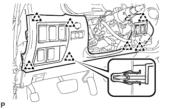
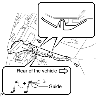
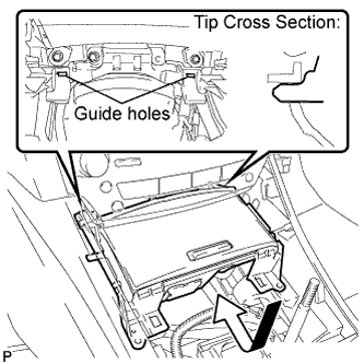
INSTALL NO. 1 INSTRUMENT PANEL UNDER COVER SUB-ASSEMBLY
-
Connect the connectors.
-
Insert the No. 1 instrument panel under cover sub-assembly into the guide as shown in the illustration.
-
Engage the 2 claws.
-
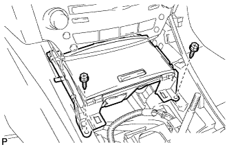
Install the No. 1 instrument panel under cover sub-assembly with the 2 screws <D>.
-
-
INSTALL SIDE INSTRUMENT PANEL LH (for LHD)
-
Engage the 5 claws and 3 clips to install the side instrument panel LH.
-
-
INSTALL FRONT DOOR OPENING TRIM COVER LH (for LHD)
-
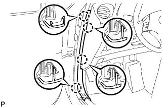
Engage the 4 claws and install the front door opening trim cover LH.
-
-
INSTALL FRONT DOOR SCUFF PLATE LH (for LHD)
-
Engage the 4 clips.
-
Engage the 7 claws and install the front door scuff plate LH.
-
-
INSTALL SIDE INSTRUMENT PANEL RH (for RHD)
-
Engage the 5 claws and 3 clips to install the side instrument panel RH.
-
-
INSTALL FRONT DOOR OPENING TRIM COVER RH (for RHD)
Tech Tips
Use the same procedure for the RH side and LH side Click here.
-
INSTALL FRONT DOOR SCUFF PLATE RH (for RHD)
Tech Tips
Use the same procedure for the RH side and LH side Click here.
-
INSTALL NO. 2 CONSOLE BOX DUCT
-
Install the No. 2 console box duct with the 2 clips.
-
-
INSTALL CONSOLE BOX
-
Engage the 2 claws and 2 clips.
-
Install the 2 bolts.
-
Install the 2 bolts.
-
Connect the connector.
-
Connect the 2 connectors.
-
Engage the 2 clamps.
-
Install the 2 bolts.
-
-
INSTALL CONSOLE BOX REGISTER ASSEMBLY
-
Engage the 2 claws and 4 clips, and then install the console box register assembly.
-
-
INSTALL REAR ASH RECEPTACLE ASSEMBLY
-
Install the rear ash receptacle assembly.
-
-
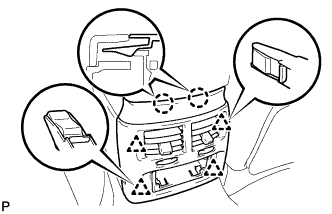
INSTALL FRONT ASH RECEPTACLE ASSEMBLY
-
Connect the connectors.
-
Insert the protruding parts of the front ash receptacle assembly into the 2 guide holes as shown in the illustration.
-
Install the front ash receptacle assembly with the 2 screws <E>.
-
-
INSTALL CONSOLE PANEL SUB-ASSEMBLY
-
Connect the connectors.
-
Engage the 8 clips to install the console panel sub-assembly.
-
-
INSTALL UPPER NO. 2 CONSOLE PANEL GARNISH
-
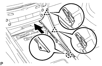
Engage the claw and 2 clips to install the upper No. 2 console panel garnish.
-
-
INSTALL UPPER NO. 1 CONSOLE PANEL GARNISH
-
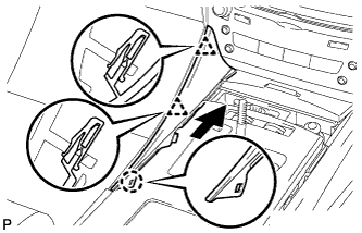
Engage the claw and 2 clips to install the upper No. 1 console panel garnish.
-
-
INSTALL SHIFT LEVER KNOB SUB-ASSEMBLY
-
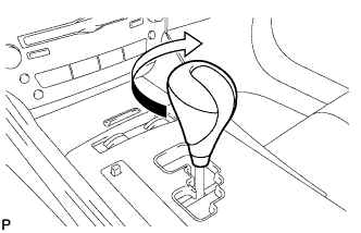
Turn the shift lever knob clockwise and install the shift lever knob sub-assembly.
-
-
INSTALL FRONT SEAT ASSEMBLY LH (for LHD)
-
Place the front seat assembly in the cabin.
Note
Be careful not to damage the vehicle body.
-
Connect the connectors under the seat.
-
Connect the cable to the negative (-) battery terminal.
Note
When disconnecting the cable, some systems need to be initialized after the cable is reconnected Click here.
-
Temporarily install the front seat assembly with the 4 bolts.
-
Operate the power seat switch knob and move the seat to the rearmost position.
-
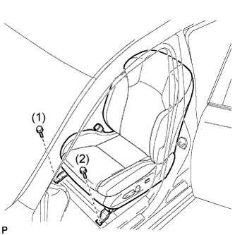
Tighten the 2 bolts on the front side of the seat.
- Torque:
- 37 N*m { 377 kgf*cm, 27 ft.*lbf }
Tech Tips
Tighten the bolts in the order indicated in the illustration.
-
Operate the power seat switch knob and move the seat to the foremost position.
-
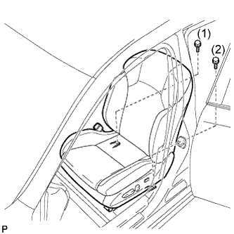
Tighten the 2 bolts on the rear side of the seat.
- Torque:
- 37 N*m { 377 kgf*cm, 27 ft.*lbf }
Tech Tips
Tighten the bolts in the order indicated in the illustration.
-
-
INSTALL REAR INNER SEAT TRACK BRACKET COVER LH (for LHD)
-
Engage the 2 claws and install the rear inner seat track bracket cover.
-
-
INSTALL REAR OUTER SEAT TRACK BRACKET COVER LH (for LHD)
-
Engage the 2 claws and install the rear outer seat track bracket cover.
-
-
INSTALL FRONT INNER SEAT TRACK BRACKET COVER LH (for LHD)
-
Operate the power seat switch knob and move the seat to the rearmost position.
-
Engage the 2 claws and install the front inner seat track bracket cover.
-
-
INSTALL FRONT OUTER SEAT TRACK BRACKET COVER LH (for LHD)
-
Engage the 2 claws and install the front outer seat track bracket cover.
-
-
INSTALL FRONT SEAT ASSEMBLY RH (for RHD)
Tech Tips
Use the same procedure for the RH side and the LH side.
-
INSTALL REAR INNER SEAT TRACK BRACKET COVER RH (for RHD)
Tech Tips
Use the same procedure for the RH side and the LH side.
-
INSTALL REAR OUTER SEAT TRACK BRACKET COVER RH (for RHD)
Tech Tips
Use the same procedure for the RH side and the LH side.
-
INSTALL FRONT INNER SEAT TRACK BRACKET COVER RH (for RHD)
Tech Tips
Use the same procedure for the RH side and the LH side.
-
INSTALL FRONT OUTER SEAT TRACK BRACKET COVER RH (for RHD)
Tech Tips
Use the same procedure for the RH side and the LH side.
-
INSTALL FRONT SEAT HEADREST ASSEMBLY
-
INSPECT FRONT SEAT ASSEMBLY
-
Check the power seat operation.
-
Check the seat heater operation.
-
Turn the engine switch on (IG).
-
Turn the seat heater switch on.
-
Wait 5 minutes or more and confirm that the seat surface becomes warm.
-
-
-
INSPECT BRAKE WARNING LIGHT
-
When operating the parking brake pedal, check that the brake warning light illuminates.
Standard The brake warning light always illuminates at the first click.
-
-
INSPECT SRS WARNING LIGHT
Tech Tips