PARKING BRAKE PEDAL INSTALLATION

-
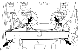
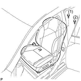
INSTALL PARKING BRAKE CONTROL PEDAL ASSEMBLY (for LHD)
-
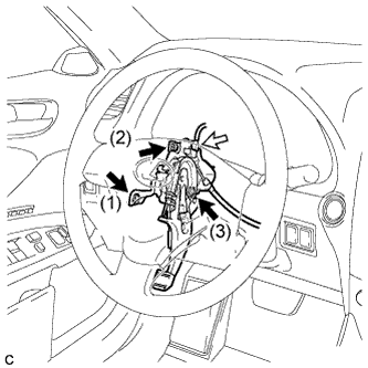
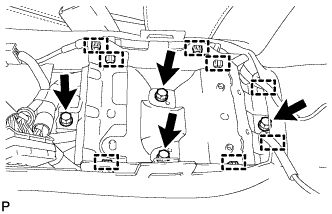
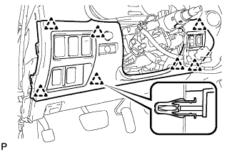
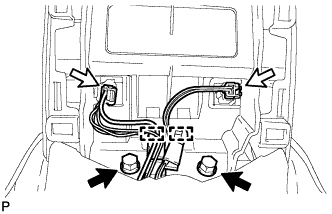
Install the parking brake control pedal assembly to the body, and temporarily tighten the 3 nuts.
-
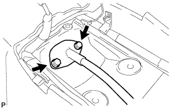
Fully tighten the 3 nuts in the order shown in the illustration.
- Torque:
- 13 N*m { 133 kgf*cm, 10 ft.*lbf }
-
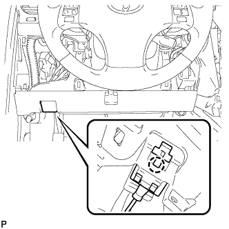
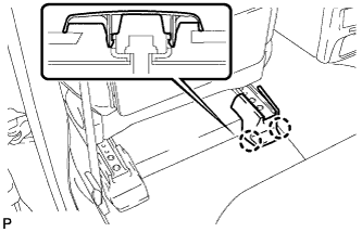
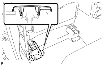
Connect the parking brake switch connector.
-
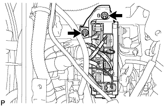
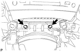
Install the instrument panel junction block assembly with the 2 nuts.
-
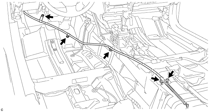
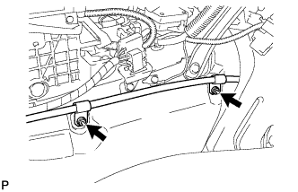
Install the No. 1 parking brake cable assembly to the body with the 3 nuts and 2 bolts.
- Torque:
- Nut
- 6.0 N*m { 61 kgf*cm, 53 in.*lbf }
- Bolt
- 8.0 N*m { 82 kgf*cm, 71 in.*lbf }
-
-
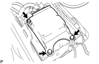
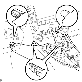
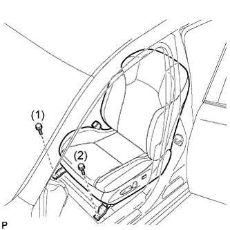
INSTALL PARKING BRAKE CONTROL PEDAL ASSEMBLY (for RHD)
-
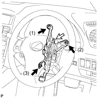
Install the parking brake control pedal assembly to the body, and temporarily tighten the bolt and 2 nuts.
-
Fully tighten the bolt and 2 nuts in the order shown in the illustration.
- Torque:
- 13 N*m { 133 kgf*cm, 10 ft.*lbf }
-
Connect the parking brake switch connector.
-
Install the No. 1 parking brake cable assembly to the body with the 2 bolts.
- Torque:
- 8.0 N*m { 82 kgf*cm, 71 in.*lbf }
-
Install the No. 1 parking brake cable assembly with the 2 nuts.
- Torque:
- 6.0 N*m { 61 kgf*cm, 53 in.*lbf }
-
-
INSTALL NO. 1 AIR DUCT (for RHD)
-
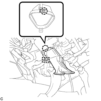
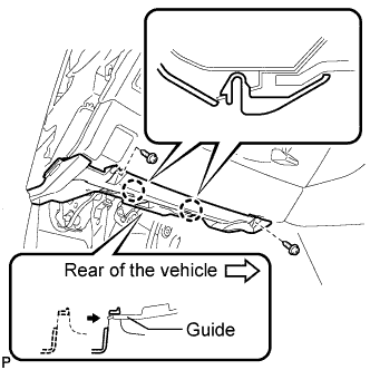
Engage the claw and guide, and install the No. 1 air duct.
-
-
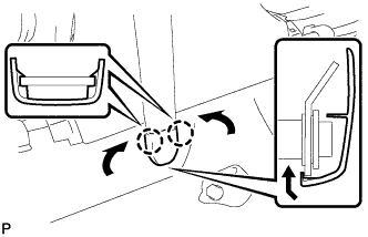
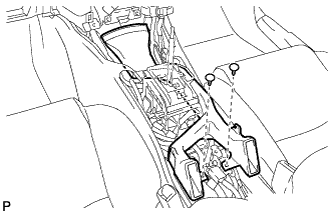
INSTALL PARKING BRAKE EQUALIZER
-
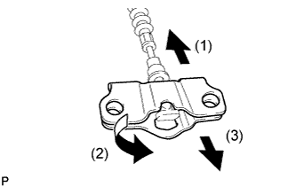
Install the parking brake equalizer to the No. 1 parking brake cable assembly in the order shown in the illustration.
-
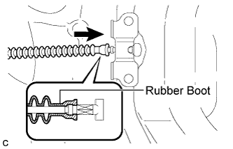
Slide the rubber boot back as shown in the illustration.
-
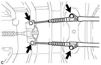
Connect the No. 2 parking brake cable assembly and No. 3 parking brake cable assembly to the parking brake equalizer.
-
Install the No. 2 parking brake cable assembly and No. 3 parking brake cable assembly to the body with the 2 bolts.
- Torque:
- 6.0 N*m { 61 kgf*cm, 53 in.*lbf }
-
-
INSTALL PARKING BRAKE RETURN WITH DAMPER SPRING
-
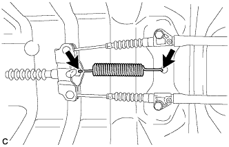
Install the parking brake return with damper spring.
-
-
INSTALL PROPELLER SHAFT WITH CENTER BEARING ASSEMBLY
Tech Tips
Refer to the instructions for Installation of the propeller shaft with center bearing assembly Click here.
-
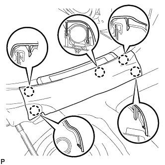
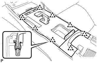
INSTALL FRONT UPPER FLOOR REAR SUB PANEL
-
Install the front upper floor rear sub panel to the body with the 4 bolts.
- Torque:
- 18 N*m { 184 kgf*cm, 13 ft.*lbf }
-
Engage the 8 clamps.
-
-
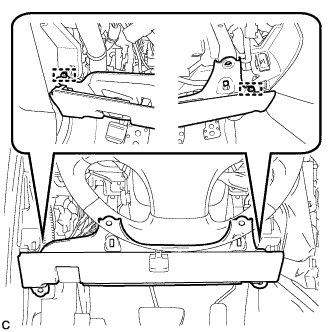
INSTALL CENTER AIRBAG SENSOR ASSEMBLY
-
Check that the engine switch is off.
-
Check that the cable is disconnected from the negative (-) battery terminal.
CAUTION:
Wait at least 90 seconds after disconnecting the cable from the negative (-) battery terminal to disable the SRS system.
-
Install the center airbag sensor assembly with the 2 bolts and nut.
- Torque:
- 18 N*m { 184 kgf*cm, 13 ft.*lbf }
Note
-
If the center airbag sensor assembly has been dropped, or there are any cracks, dents or other defects in the case or connector, replace it with a new one.
-
When installing the center airbag sensor assembly, be careful that the SRS wiring does not interfere with other parts and that it is not pinched between other parts.
-
When the engine switch is first turned on (IG) after the center airbag sensor assembly has been replaced, make sure that no one is in the vehicle.
-
Connect the holder (with connectors).
Note
When connecting the airbag connector, take care not to damage the airbag wire harness.
-
Check that the waterproof sheet is properly set.
-
Check that there is no looseness in the installation parts of the center airbag sensor assembly.
-
-
INSTALL NO. 2 REAR AIR DUCT (for LHD)
-
INSTALL NO. 1 REAR AIR DUCT (for RHD)
-
INSTALL REAR AIR DUCT GUIDE LH (for LHD)
-
INSTALL REAR AIR DUCT GUIDE RH (for RHD)
-
INSTALL FRONT FLOOR SILENCER PAD LH (for LHD)
-
INSTALL FRONT FLOOR SILENCER PAD RH (for RHD)
-
INSTALL NO. 3 DASH PANEL INSULATOR PAD
-
Install the No. 3 dash panel insulator pad with the clip.
-
-
INSTALL FRONT FLOOR FOOTREST LH (for LHD)
-
Engage the 2 clips and install the front floor footrest LH.
-
-
INSTALL FRONT FLOOR FOOTREST RH (for RHD)
-
Engage the 2 clips and install the front floor footrest RH.
-
-
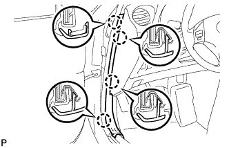
INSTALL LOWER CENTER PILLAR GARNISH LH (for LHD)
-
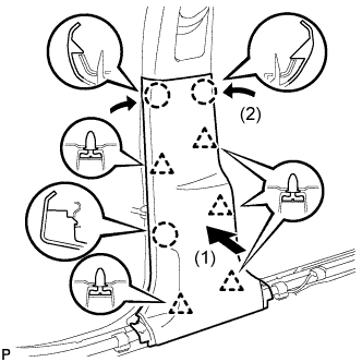
Engage the 5 clips and 3 claws, and install the lower center pillar garnish LH.
-
-
INSTALL FRONT SEAT OUTER BELT ASSEMBLY LH (for LHD)
-
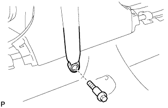
Install the front seat outer belt assembly LH with the bolt.
- Torque:
- 42 N*m { 428 kgf*cm, 31 ft.*lbf }
-
-
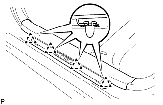
INSTALL REAR DOOR SCUFF PLATE LH (for LHD)
-
Engage the 2 clips.
-
Engage the 5 claws and install the rear door scuff plate LH.
-
-
INSTALL LOWER CENTER PILLAR GARNISH RH (for RHD)
Tech Tips
Use the same procedure for the RH side and the LH side.
-
INSTALL FRONT SEAT OUTER BELT ASSEMBLY RH (for RHD)
Tech Tips
Use the same procedure for the RH side and the LH side.
-
INSTALL REAR DOOR SCUFF PLATE RH (for RHD)
Tech Tips
Use the same procedure for the RH side and the LH side.
-
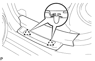
INSTALL LAP BELT OUTER ANCHOR COVER
-
Engage the 2 claws and install the lap belt outer anchor cover as shown in the illustration.
Tech Tips
Use the same procedure to install the cover on the other side.
-
-
INSTALL DRIVER SIDE KNEE AIRBAG ASSEMBLY
-
Check that the engine switch is off.
-
Check that the battery negative (-) cable is disconnected.
CAUTION:
Wait at least 90 seconds after disconnecting the cable from the negative (-) battery terminal to disable the SRS system.
-
Connect the driver side knee airbag connector to the driver side knee airbag assembly.
Note
When connecting the airbag connector, take care not to damage the airbag wire harness.
-
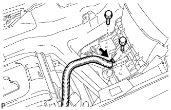
Temporarily install the driver side knee airbag assembly with the 2 pins.
-
Install the driver side knee airbag assembly with the 4 bolts.
- Torque:
- 10 N*m { 102 kgf*cm, 7 ft.*lbf }
-
Install the hood lock control cable with the claw.
-
-
INSTALL LOWER INSTRUMENT PANEL FINISH PANEL SUB-ASSEMBLY
-
Connect the connectors.
-
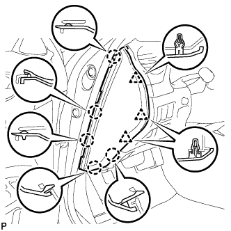
Engage the 7 clips to install the lower instrument panel finish panel sub-assembly.
-
-
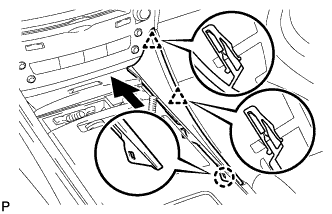
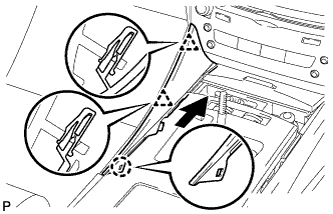
INSTALL NO. 1 INSTRUMENT PANEL UNDER COVER SUB-ASSEMBLY
-
Connect the connectors.
-
Insert the No. 1 instrument panel under cover sub-assembly into the guide as shown in the illustration.
-
Engage the 2 claws.
-
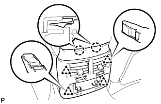
Install the No. 1 instrument panel under cover sub-assembly with the 2 screws <D>.
-
-
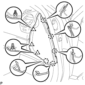
INSTALL SIDE INSTRUMENT PANEL LH (for LHD)
-
Engage the 5 claws and 3 clips to install the side instrument panel LH.
-
-
INSTALL FRONT DOOR OPENING TRIM COVER LH (for LHD)
-
Engage the 4 claws and install the front door opening trim cover LH.
-
-
INSTALL FRONT DOOR SCUFF PLATE LH (for LHD)
-
Engage the 4 clips.
-
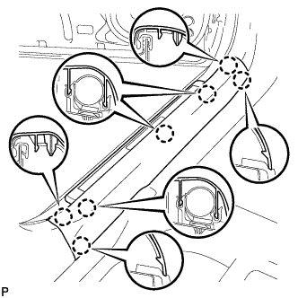
Engage the 7 claws and install the front door scuff plate LH.
-
-
INSTALL SIDE INSTRUMENT PANEL RH (for RHD)
-
Engage the 5 claws and 3 clips to install the side instrument panel RH.
-
-
INSTALL FRONT DOOR OPENING TRIM COVER RH (for RHD)
Tech Tips
Use the same procedure for the RH side and LH side Click here.
-
INSTALL FRONT DOOR SCUFF PLATE RH (for RHD)
Tech Tips
Use the same procedure for the RH side and LH side Click here.
-
INSTALL NO. 2 CONSOLE BOX DUCT
-
Install the No. 2 console box duct with the 2 clips.
-
-
INSTALL CONSOLE BOX
-
Engage the 2 claws and 2 clips.
-
Install the 2 bolts.
-
Install the 2 bolts.
-
Connect the connector.
-
Connect the 2 connectors.
-
Engage the 2 clamps.
-
Install the 2 bolts.
-
-
INSTALL CONSOLE BOX REGISTER ASSEMBLY
-
Engage the 2 claws and 4 clips, and then install the console box register assembly.
-
-
INSTALL REAR ASH RECEPTACLE ASSEMBLY
-
Install the rear ash receptacle assembly.
-
-
INSTALL FRONT ASH RECEPTACLE ASSEMBLY
-
Connect the connectors.
-
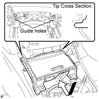
Insert the protruding parts of the front ash receptacle assembly into the 2 guide holes as shown in the illustration.
-
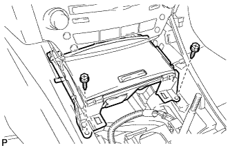
Install the front ash receptacle assembly with the 2 screws <E>.
-
-
INSTALL CONSOLE PANEL SUB-ASSEMBLY
-
Connect the connectors.
-
Engage the 8 clips to install the console panel sub-assembly.
-
-
INSTALL UPPER NO. 2 CONSOLE PANEL GARNISH
-
Engage the claw and 2 clips to install the upper No. 2 console panel garnish.
-
-
INSTALL UPPER NO. 1 CONSOLE PANEL GARNISH
-
Engage the claw and 2 clips to install the upper No. 1 console panel garnish.
-
-
INSTALL SHIFT LEVER KNOB SUB-ASSEMBLY
-
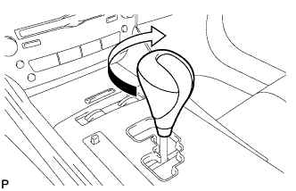
Turn the shift lever knob clockwise and install the shift lever knob sub-assembly.
-
-
INSTALL FRONT SEAT ASSEMBLY LH (for LHD)
-
Place the front seat assembly in the cabin.
Note
Be careful not to damage the vehicle body.
-
Connect the connectors under the seat.
-
Connect the cable to the negative (-) battery terminal.
Note
When disconnecting the cable, some systems need to be initialized after the cable is reconnected Click here.
-
Temporarily install the front seat assembly with the 4 bolts.
-
Operate the power seat switch knob and move the seat to the rearmost position.
-
Tighten the 2 bolts on the front side of the seat.
- Torque:
- 37 N*m { 377 kgf*cm, 27 ft.*lbf }
Tech Tips
Tighten the bolts in the order indicated in the illustration.
-
Operate the power seat switch knob and move the seat to the foremost position.
-
Tighten the 2 bolts on the rear side of the seat.
- Torque:
- 37 N*m { 377 kgf*cm, 27 ft.*lbf }
Tech Tips
Tighten the bolts in the order indicated in the illustration.
-
-
INSTALL REAR INNER SEAT TRACK BRACKET COVER LH (for LHD)
-
Engage the 2 claws and install the rear inner seat track bracket cover.
-
-
INSTALL REAR OUTER SEAT TRACK BRACKET COVER LH (for LHD)
-
Engage the 2 claws and install the rear outer seat track bracket cover.
-
-
INSTALL FRONT INNER SEAT TRACK BRACKET COVER LH (for LHD)
-
Operate the power seat switch knob and move the seat to the rearmost position.
-
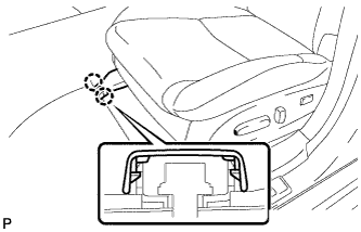
Engage the 2 claws and install the front inner seat track bracket cover.
-
-
INSTALL FRONT OUTER SEAT TRACK BRACKET COVER LH (for LHD)
-
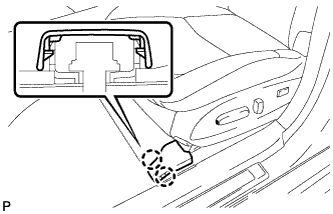
Engage the 2 claws and install the front outer seat track bracket cover.
-
-
INSTALL FRONT SEAT ASSEMBLY RH (for RHD)
Tech Tips
Use the same procedure for the RH side and the LH side.
-
INSTALL REAR INNER SEAT TRACK BRACKET COVER RH (for RHD)
Tech Tips
Use the same procedure for the RH side and the LH side.
-
INSTALL REAR OUTER SEAT TRACK BRACKET COVER RH (for RHD)
Tech Tips
Use the same procedure for the RH side and the LH side.
-
INSTALL FRONT INNER SEAT TRACK BRACKET COVER RH (for RHD)
Tech Tips
Use the same procedure for the RH side and the LH side.
-
INSTALL FRONT OUTER SEAT TRACK BRACKET COVER RH (for RHD)
Tech Tips
Use the same procedure for the RH side and the LH side.
-
INSTALL FRONT SEAT HEADREST ASSEMBLY
-
INSTALL REAR SEAT CUSHION ASSEMBLY
-
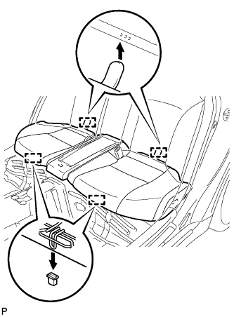
Engage the 2 rear hooks of the seat cushion to the child restraint seat anchor bracket.
-
Engage the 2 front hooks of the seat cushion to the vehicle body.
-
Confirm that the seat cushion is firmly installed.
Note
When installing the seat cushion, make sure the seat belt buckle is not under the seat cushion.
-
-
INSPECT FRONT SEAT ASSEMBLY
-
Check the power seat operation.
-
Check the seat heater operation.
-
Turn the engine switch on (IG).
-
Turn the seat heater switch on.
-
Wait 5 minutes or more and confirm that the seat surface becomes warm.
-
-
-
ADJUST PARKING BRAKE SHOE CLEARANCE AND PARKING BRAKE PEDAL TRAVEL
-
Remove the No. 1 instrument panel under cover sub-assembly Click here.
-
Completely release the parking brake pedal.
-
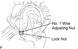
Loosen the lock nut and No. 1 wire adjusting nut to completely release the parking brake cable.
-
Remove the rear wheel.
-
Temporarily install the hub nuts.
-
Remove the shoe adjusting hole plug.
-
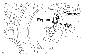
Turn the shoe adjuster and expand the shoe until the disc locks.
-
Turn and contract the shoe adjuster until the disc can rotate smoothly.
Standard Return 7 notches. -
Check that there is no brake drag against the shoe.
-
Install the shoe adjusting hole plug.
-
Turn the adjusting nut until the parking brake pedal travel is corrected to be within the specified range.
Parking brake pedal travel 7 to 9 notches at 300 N (31 kgf, 67.5 lbf) -
Using a wrench or an equivalent tool, hold the adjusting nut and tighten the lock nut.
- Torque:
- 7.0 N*m { 71 kgf*cm, 62 in.*lbf }
-
Operate the parking brake pedal 3 to 4 times, and check the parking brake pedal travel.
-
Check that there is no brake drag against the shoe.
-
Remove the hub nuts.
-
Install the rear wheel.
- Torque:
- 103 N*m { 1050 kgf*cm, 76 ft.*lbf }
-
Install the No. 1 instrument panel under cover sub-assembly Click here.
-
-
INSPECT BRAKE WARNING LIGHT
-
When operating the parking brake pedal, check that the brake warning light illuminates.
Standard The brake warning light always illuminates at the first click.
-
-
INSPECT SRS WARNING LIGHT