REAR WHEEL ALIGNMENT ADJUSTMENT

Note
If the wheel alignment has been adjusted, or if suspension or underbody components have been removed/installed or replaced, be sure to perform the following initialization procedure in order for the system to function normally:
-
Disconnect the cable from the negative battery terminal for more than 2 seconds.
-
Reconnect the cable to the negative battery terminal.
-
Perform zero point calibration of the yaw rate and acceleration sensor and test mode inspection.
Tech Tips
-
INSPECT REAR SUSPENSION
-
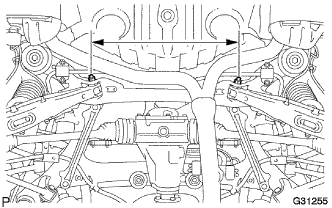
Inspect the rear suspension member.
-
Measure the distance between the centers of the installation bolts of the rear No. 2 suspension arm assembly LH and RH.
Standard 508.6 to 514.6 mm (20.02 to 20.25 in.) If the distance is not within the specified range, replace the rear suspension member.
-
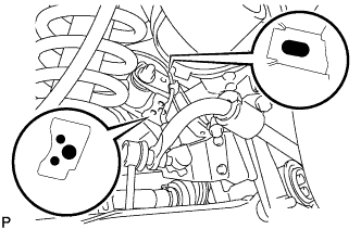
Visually inspect the press holes on the installation area of the rear upper No. 2 control arm assembly.
Standard The holes are not deformed. If the holes are deformed, replace the rear suspension member.
-
-
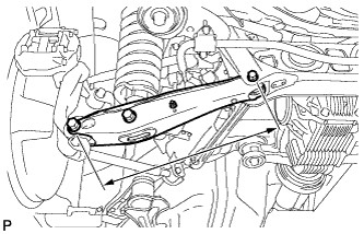
Inspect the rear No. 2 suspension arm assembly.
-
Measure the distance between the centers of the 2 installation bolts of the rear No. 2 suspension arm assembly.
Standard 433.4 to 434.4 mm (17.063 to 17.102 in.) If the distance is not within the specified range, replace the rear No. 2 suspension arm assembly.
-
-
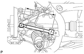
Inspect the rear upper No. 2 control arm assembly.
-
Measure the distance between the centers of the installation bolt of the rear upper No. 2 control arm assembly and the ball joint stud.
Standard 310.6 to 312.0 mm (12.2 to 12.3 in.) If the distance is not within the specified range, replace the rear upper No. 2 control arm assembly.
-
-
Inspect and adjust the toe-in and camber.
-
Inspect the toe-in and camber.
If the values are not within the specified ranges, adjust the installation bolt holding the rear suspension member to the vehicle body, or the bolt holding the upper control arm and rear suspension arm so that the values fall within the specified ranges.
-
-
-
INSPECT TIRES
-
Check the tires for wear and proper inflation pressure.
Cold Tire Inflation Pressure Tire Size Cold Tire Inflation Pressure
kPa (kgf/cm2, psi)
Front Rear Front Rear 225/40R19 93Y 255/35R19 96Y 320 (3.2, 46)*1
300 (3.0, 44)*2
250 (2.5, 36)*3
320 (3.2, 46)*1
300 (3.0, 44)*2
250 (2.5, 36)*3
*1: For driving at over 250 km/h (155 mph).
*2: For driving at 210 km/h (131 mph) to 250 km/h (155 mph).
*3: For driving at under 210 km/h (131 mph).
-
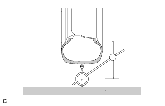
Using a dial indicator, check the runout of the tires.
Maximum tire runout 1.0 mm (0.0394 in.)
-
-
MEASURE VEHICLE HEIGHT
-
Bounce the vehicle at the corners up and down to stabilize the suspension and inspect the vehicle height.
Note
-
Before inspecting the wheel alignment, adjust the vehicle height to the specified value.
-
Be sure to perform measurement on a level surface.
-
If it is required to go under the vehicle for measurement, confirm that the parking brake is applied and the vehicle is secured with chocks.
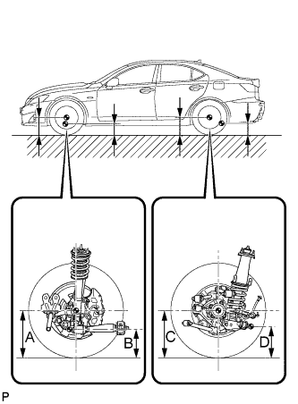
Vehicle Height Front A-B Rear C-D 131.7 mm (5.19 in.) 112.1 mm (4.41 in.) Measuring points A Ground clearance of front wheel center. B Ground clearance of front center position of front suspension lower arm assembly front bushing installation bolt head. C Ground clearance of rear center position of rear No. 2 suspension arm bushing installation bolt threads. D Ground clearance of rear center position of rear suspension lower arm assembly rear bushing installation bolt head. -
-
-
INSPECT TOE-IN
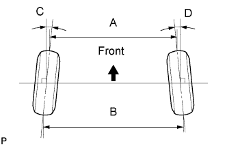
Toe-in Toe-in (Total) C + D: 0°16' +/- 10' (0.26°+/- 0.17°)
B - A: 3 +/- 2 mm (0.118 +/- 0.0787 in.)
Tech Tips
Measure "B - A" only when "C + D" cannot be measured.
If the toe-in is not within the specified range, inspect the suspension parts and replace parts if necessary.
-
ADJUST TOE-IN
-
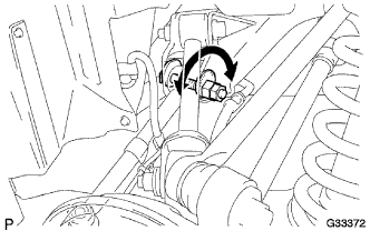
Loosen the toe adjust cam nut.
-
Turn the adjust cams by an equal amount to adjust the toe-in.
Tech Tips
-
Try to adjust the toe-in to the center value.
-
The toe-in will change by the following amount corresponding to each graduation of the cam:
Approx. 4.0 mm (0.16 in.)
-
-
Tighten the nut.
- Torque:
- 50 N*m { 510 kgf*cm, 37 ft.*lbf }
-
-
INSPECT CAMBER
-
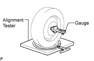
Install a camber-caster-kingpin gauge or put the rear wheels on a wheel alignment tester.
-
Inspect the camber.
Camber Camber Angle -0°47' +/- 45' (- 0.78° +/- 0.75°) Note
-
Inspect while the vehicle is unloaded.
-
The maximum tolerance of right and left difference for the camber is 30' (0.5°) or less.
If the measured value is not within the specified range, inspect the suspension parts for damage and wear. Replace parts as necessary because camber cannot be properly adjusted with any damaged or worn parts.
-
-
-
PLACE FRONT WHEELS FACING STRAIGHT AHEAD
-
DISCONNECT CABLE FROM NEGATIVE BATTERY TERMINAL
Note
Disconnect the cable from the negative battery terminal for more than 2 seconds.
-
CONNECT CABLE TO NEGATIVE BATTERY TERMINAL
Note
When disconnecting the cable, some systems need to be initialized after the cable is reconnected Click here.
-
PERFORM YAW RATE SENSOR ZERO POINT CALIBRATION
Tech Tips
Perform yaw rate sensor zero point calibration Click here.
-
CHECK STEERING ANGLE SENSOR ZERO POINT CALIBRATION
Tech Tips
Check steering angle sensor zero point calibration Click here.