REAR AXLE HUB BOLT REPLACEMENT

Tech Tips
-
Use the same procedure for the RH side and LH side.
-
The procedure listed below is for the LH side.
-
REMOVE REAR WHEEL
-
SEPARATE REAR DISC BRAKE CYLINDER ASSEMBLY
-
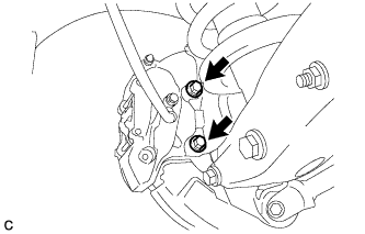
Remove the 2 bolts and separate the rear disc brake cylinder assembly.
Note
Hang the caliper with wire or equivalent.
-
-
REMOVE REAR DISC
-
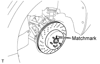
Put matchmarks on the rear disc and rear axle hub.
-
Release the parking brake and remove the rear disc.
Tech Tips
If the disc cannot be removed easily, turn and press firmly the shoe adjuster until the wheel comes free.
-
-
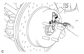
REMOVE REAR AXLE HUB BOLT
-
Temporarily install 2 nuts and 2 washers to the rear axle hub bolt as shown in the illustration.
Tech Tips
Install hub nuts to prevent damage to the hub bolts.
-
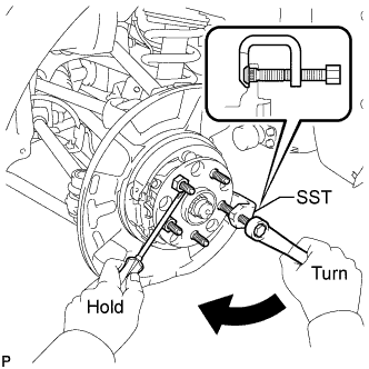
Using SST and a screwdriver or an equivalent tool to hold the rear axle hub and bearing assembly, remove the rear axle hub bolt.
- SST
- 09628-10011
Note
Do not damage the threads of the rear axle hub bolts.
-
-
INSTALL REAR AXLE HUB BOLT
-
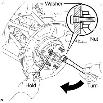
Install a washer and nut to a new rear axle hub bolt as shown in the illustration.
-
Using a screwdriver or an equivalent tool to hold the rear axle hub and bearing assembly, install the rear axle hub bolt by tightening the nut.
Note
Do not damage the threads of the rear axle hub bolts.
Tech Tips
Install hub nuts to prevent damage to the hub bolts.
-
-
INSTALL REAR DISC
-
Align matchmarks of the rear disc and rear axle hub, and install the rear disc.
Note
When replacing the disc with a new one, select the installation position where the rear disc has minimal runout.
-
-
INSTALL REAR DISC BRAKE CYLINDER ASSEMBLY
-
Install the rear disc brake cylinder assembly to the rear axle carrier with the 2 bolts.
- Torque:
- 54 N*m { 551 kgf*cm, 40 ft.*lbf }
Note
-
Do not twist the brake hose.
-
Make sure that the bolts are free from damage and foreign matter.
-
Do not overtighten the bolts.
-
-
ADJUST PARKING BRAKE SHOE CLEARANCE AND PARKING BRAKE PEDAL TRAVEL
-
Remove the No. 1 instrument panel under cover sub-assembly Click here.
-
Completely release the parking brake pedal.
-
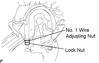
Loosen the lock nut and No. 1 wire adjusting nut to completely release the parking brake cable.
-
Remove the rear wheel.
-
Temporarily install the hub nuts.
-
Remove the shoe adjusting hole plug.
-
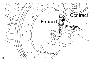
Turn the shoe adjuster and expand the shoe until the disc locks.
-
Turn and contract the shoe adjuster until the disc can rotate smoothly.
Standard Return 7 notches. -
Check that there is no brake drag against the shoe.
-
Install the shoe adjusting hole plug.
-
Turn the adjusting nut until the parking brake pedal travel is corrected to be within the specified range.
Parking brake pedal travel 7 to 9 notches at 300 N (31 kgf, 67.5 lbf) -
Using a wrench or an equivalent tool, hold the adjusting nut and tighten the lock nut.
- Torque:
- 7.0 N*m { 71 kgf*cm, 62 in.*lbf }
-
Operate the parking brake pedal 3 to 4 times, and check the parking brake pedal travel.
-
Check that there is no brake drag against the shoe.
-
Remove the hub nuts.
-
Install the rear wheel.
- Torque:
- 103 N*m { 1050 kgf*cm, 76 ft.*lbf }
-
Install the No. 1 instrument panel under cover sub-assembly Click here.
-
-
INSTALL REAR WHEEL
- Torque:
- 103 N*m { 1050 kgf*cm, 76 ft.*lbf }